


84
Service Manual
Third edition, June 1997
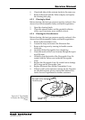
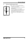
When checking the resistance of a Pt 100 sensor, observe the
additional resistance of the connecting leads, which can be
either in a 3-wire or 4-wire configuration.
Note: For service of temperature sensors, strictly observe the safety
regulations for intrinsic safety, see chapter 2.1.
Use a certified battery operated multipurpose instrument to
check the resistance of the Pt 100 element. The cable leads are
colored according to the DIN Standard - white, (white), red
and red.
1. Begin by opening the cover of the Temperature Connec-
tion Box and disconnect the leads to the Pt 100 element
you want to check.
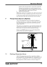
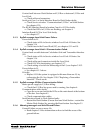
2. Measure the resistance between two red cable leads to
establish the lead resistance (B). Then measure the
resistance between white and red leads to get the total
resistance (A). The resistance of the Pt 100 elements:
R
Pt
= A-B Ω
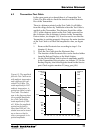
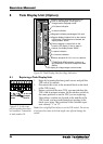
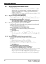
Check corresponding temperature in figure 7-3. If the
derived temperature (R
Pt
) is not equal to the actual
temperature, replace the Pt 100 element.
3. Check the insulation to ground. Measure the resistance
from each of the leads to the inside of the Temperature
Connection Box. If any resistance is below 10 MΩ,
replace the Pt 100 element. See also chapter 9.14.
white*
red*
red*
* DIN Standard
R
Pt 100
A
B
white* (Only on
4-wire sensor)
100
Resistance
(Ohm)
0 10203040506070
Temp
(°C)
105
110
115
120
125
130
80
Figure 7-3. Relation
between temperature and
resistance.
Figure 7-2.