


60
Service Manual
Third edition, June 1997
1
0
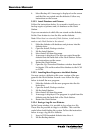
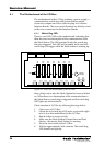
F1
2A
F2
1A
F3
2A
F4
2A
F5
1A
F6
2A
NEMKO Nr Ex 94C346 (EEx ia)IIC
SERVICE PC
CONNECTOR
F8-8A
F7-2A
(SERVICE POWER)
SERVICE
POWER
S1
LP Power Block
9150 064-641
POWER SUPPLY
115 VAC
230 VAC
F1-F6= LI Power Fuses.
WARNING: Any substitution
of components may impair
intrinsic safety. See Service
Manual.
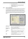
OPEN HERE
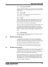
A
PORT 1
B
CENT 1
C
STBD 1
1
PORT 2
CENT 2
STBD 2
PORT 3
CENT 3
STBD 3
PORT 4
CENT 4
STBD 4
PORT 5
CENT 5
STBD 5
2 3 4 5
POWER SUPPLY
A
PORT 1
B
CENT 1
C
STBD 1
1
PORT 2
CENT 2
STBD 2
PORT 3
CENT 3
STBD 3
PORT 4
CENT 4
STBD 4
PORT 5
CENT 5
STBD 5
2 3 4 5
POWER SUPPLY
NEMKO Nr. Ex 94C346(Exia)IIC
Transmitter Cable Data:
Lmax=500 µH, Cmax=100 µF
POWER SUPPLY
GROUND
FAILURE
NEMKO Nr. Ex 94C346(Exia)IIC
Transmitter Cable Data:
Lmax=500 µH, Cmax=100 µF
GROUND
FAILURE
7 8 9 0
4 5 6
1 2 3
ALARM
SYSTEM
MENU
SERV
ENTER
CLEAR
OK i
1 2 3
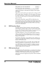
LCP LCM
LCS
LCM
LCS
LCI
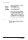
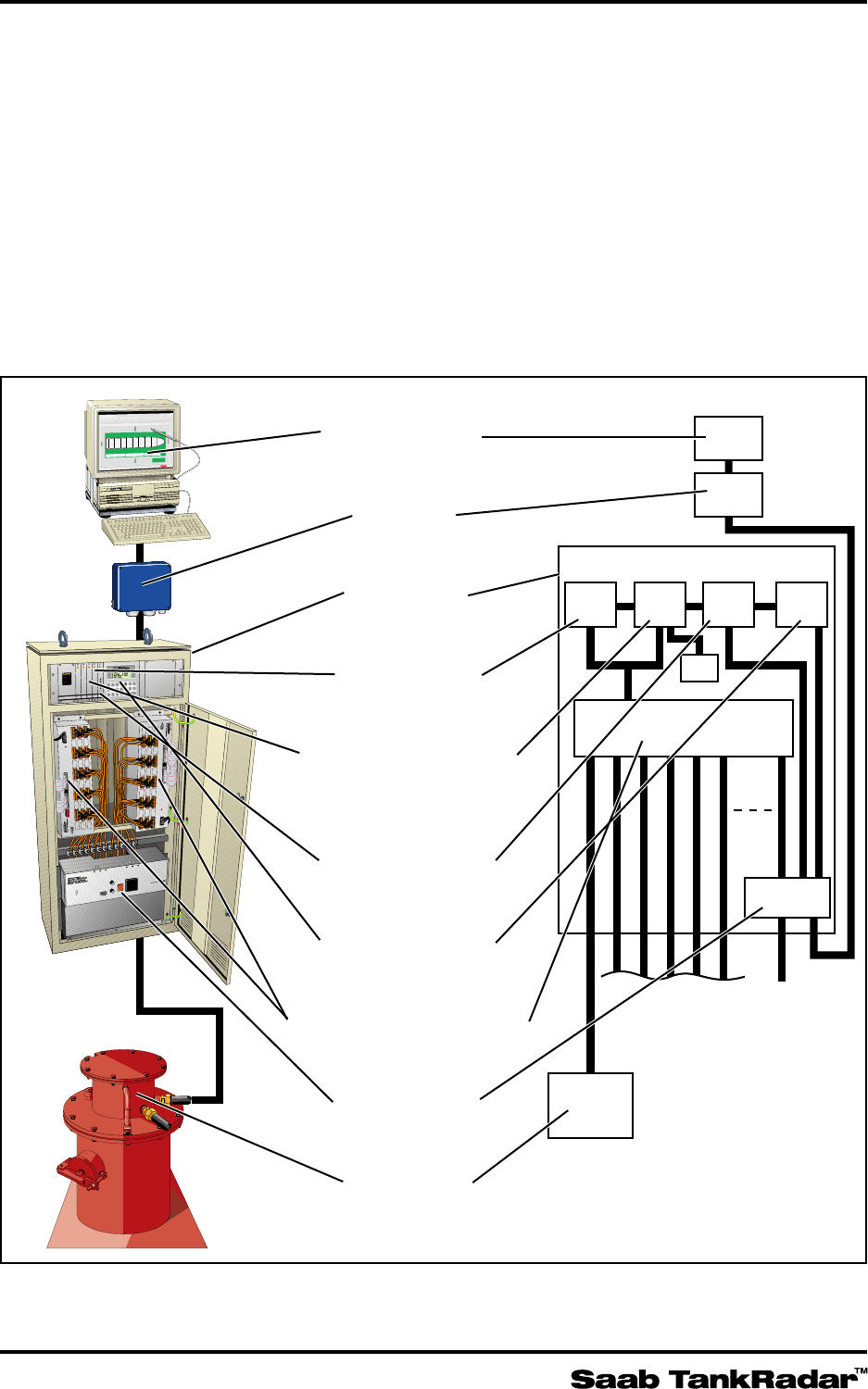
Work Station
I/O Box
Level Unit
Signal Board
Processor Memory
Board
Interface Board
Backup Display
Transmitter Interface
Power Block
Transmitter
LCM
WS
LCI LCB
LI
TX
LU
LCS
LP
Power
T/L
I/O
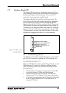
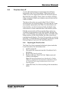
Figure 5-2 shows the information flow in the Saab TankRadar system.
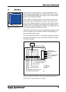
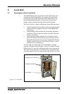
Saab TankRadar
Mon Jan 13 11:26:56
1994
CT 1 Ullage ( 1.219)
Window
Alarm
Silent
Accept
Owerview
Ballast
Trin/List
Groups
Cargo
Help
Exit
Back
Overview
7.28
List 0.0 Degree
Trim 9.95 Meter
2.31
12.26
CT 1,2 and 3CT 4 ,5 and 6CT 7, 8, 9, SlPt and SlSb
Sl
Pt
Sl
Sb
CT 9
2.860
CT 8
4.500
CT 7
11.789
CT 5
10.480
CT 4
11.042
CT 3
12.451
CT 2
8.728
CT 1
1.050
CT 6
8.099
14.340
14.013
7.28
Exit all
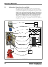
5.2 Information Flow within the Level Unit
The signals from a Transmitter enter the Level Unit into a
Transmitter Interface (LI) where they pass the zener barriers
and go on to the Signal Board (LCS). The components on the
Signal Board amplify and process the signals. The signals are
converted to digital form by the Signal Board and are sent to
the Processor Memory Board (LCM), where the signals are
digitally processed. The Interface Board (LCI) handles the
communication between the Level Unit and the Work Sta-
tion, the Backup Display, the I/O Box and a Service PC if one
is connected.