


77
Service Manual
Third edition, June 1997
6.2 Transmitter Test Cable
In the spare parts set on board there is a Transmitter Test
Cable. Use this cable to check the function of the Electronic
Box of the Transmitter.
There is a distance printed on the Test Cable. It will differ
from the ullage shown by TankRadar when the Test Cable is
applied on the Transmitter. The distance should be within
±10 % of the distance stated on the Test Cable corrected for
the A-distance (the A-distance is shown in the Transmitter
Data-window, see chapter 3.9). It can be used to see that the
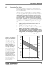
Transmitter is working properly. However, the main function
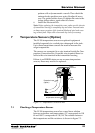
of the Test Cable is to check the amplitude value, see figure
6-3.
1. Remove the Electronic box according to steps 1-3 in
chapter 6.1 above.
2. Place the Test Cable into the Electronic Box.
3. The function of the Electronic Box can be checked either
from the Backup Display or the Work Station.
4. On the Work Station, check value of amplitude postfilt
in the Transmitter Data-window, see chapter 3.9. On the
Backup Display, check the Register-frame in the Service
part. Check register number 21 (amp_post_filt).
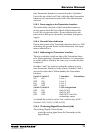
500
600
700
800
1000
900
1500
2000
2500
3000
4000
5000
Amplitude
(mV)
-30-20-100 10203040506070
Temp
(°C)
600
700
800
1000
900
1500
2000
2500
3000
4000
5000
Amplitude
(mV)
1600
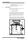
Figure 6-3. The amplitude
from the Test Cable varies
with ambient temperature
and is different for indi-
vidual Test Cables. The
rated amplitude for 20
°
C
ambient temperature, is
printed on a label on each
Test Cable. The shaded
area in the diagram shows
the acceptable amplitude
for a Test Cable with a
rated amplitude of 2000
mV. When the amplitude
printed on the label is
other than 2000 mV, the
shaded area can be moved
up or down so that its
centre corresponds to its
printed amplitude.