


57
Service Manual
Third edition, June 1997
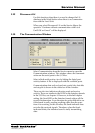
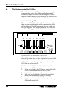
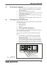
4.1.2 Communication LEDs
A green LED (H2) indicates received data and a yellow LED
(H3) indicates transmitted data. Received data is echoed back
to the source.
4.1.3 Power LED
The voltages on the motherboard are monitored and are
indicated by a green LED (H1).
4.1.4 Relays
There are eight relays for alarms and general output signals
in the I/O Box. One of them is a System Failure relay con-
trolled by the Work Station. The other seven relays can be
used for alarms or for general output signals.
There is a similar set of relays in the Power Block of the Level
Unit. However, the System Failure relay in the I/O Box is
activated by System Failures from both the Level Unit and
the Work Station, while the System Failure relay in the Power
Block is activated only by System Failures within the Level
Unit.
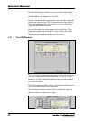
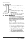
4.1.5 Power Setting
On the motherboard there is a switch for selecting the power
as either 230 VAC or as 115 VAC.
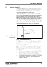
4.2 RS-232 Interface Board
The RS-232 Interface Board is used to connect equipment
with RS-232 communication to the I/O Box. The Interface
Board provides galvanic separation of the signals to the Work
Station. No conversion of the RS-232 signals is made.
The Interface Board has a green LED for indication of re-
ceived signals and a yellow LED for transmitted signals.
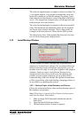
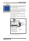
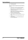
4.3 RS 485 Interface Board
The RS 485 Interface Board is used for connecting equipment
with RS 485 communication to the I/O Box. The Interface
Board converts the signal from RS-232 to RS 485 and back to
RS-232, as well as providing galvanic isolation.
The RS 485 Interface Board can be set in two different modes:
half duplex or full duplex by setting jumpers on the board.
The jumpers also control the 485-bus end termination. The
default setting of a spare board is half duplex and end termi-
nated. The jumper settings are: