


70
Service Manual
Third edition, June 1997
5.9.7 Amplitude Frame
This frame is used for viewing the amplitude of the tank
signal. The frame shows three amplitude values at a time.
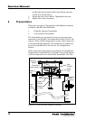
5.10 Transmitter Interface, LI
The Transmitter Interfaces provide intrinsically safe power to
the Transmitters, temperature sensors, IG pressure measure-
ment and Local Displays on deck.
5.10.1 Cabling
The cables from the Transmitters are connected to the Trans-
mitter Interfaces in the Level Unit. The Transmitters are
connected with individual jackable terminals.
5.10.2 Configuration of the Transmitter Interfaces
The Transmitter Interface is made up of two types of printed
circuit boards, the Analog/Digital/Power Board (LIA) and
the Zener Barrier Board (LIZ).
In each Transmitter Interface there can be one, two or three
LIZ boards. Each board can connect up to five Transmitters.
Each Transmitter Interface can connect up to 15 Transmitters.
There can be one or two Transmitter Interfaces in the Level
Unit.
For example, a system with 18 tanks would have one Level
Unit with two Transmitter Interfaces. There would be four
LIZ boards in these two Transmitter Interfaces together.
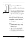
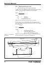
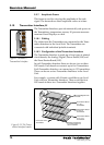
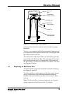
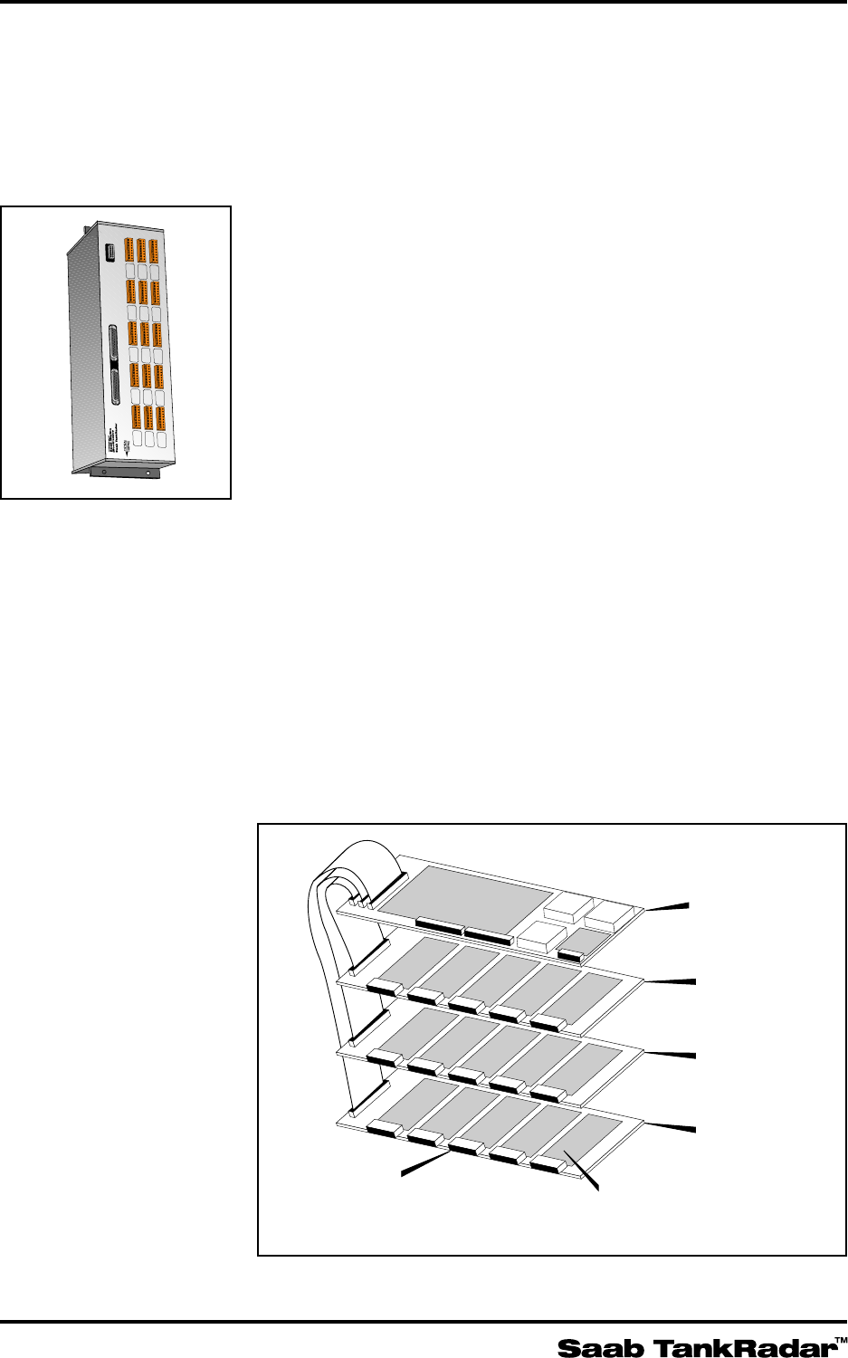
Figure 5-11. The Trans-
mitter Interface boards.
Analog/Digital/Power
Board
Zener Barrier Board
for 1 to 5
Transmitters
Zener Barrier Board
for 6 to 10
Transmitters
Zener Barrier Board
for 11 to 15
Transmitters
Separate circuits with
four zener barriers for
each Transmitter
Connectors for the
Transmitters
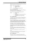
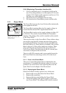
A
PORT 1
B
CENT 1
C
STBD 1
1
PORT 2
CENT 2
STBD 2
PORT 3
CENT 3
STBD 3
PORT 4
CENT 4
STBD 4
PORT 5
CENT 5
STBD 5
2 3 4 5
LI LEVEL INTERFACE
9150064-631
POWER SUPPLY
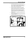
Figure 5-10 shows a
Transmitter Interface.