


59
Service Manual
Third edition, June 1997
5 Level Unit
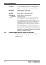
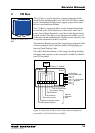
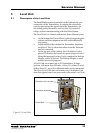
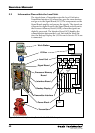
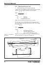
5.1 Description of the Level Unit
The Level Unit contains terminals for the intrinsically safe
connection of the Transmitters. It contains the electronics
used for processing the signals from the Transmitters, for
calculating tank parameters, such as trim/list corrected
ullage, and for communicating with the Work Station.
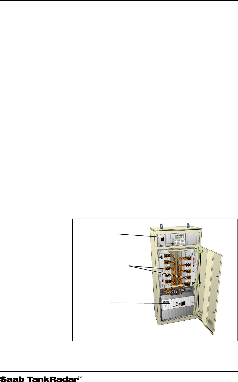
The Level Unit is a cabinet with mainly three different parts.
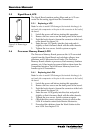
• At the bottom the Power Block is placed supplying the
cabinet and the equipment on deck with intrinsically
safe power.
• In the middle of the cabinet the Transmitter Interfaces
are placed. This is where the cables from the Transmit-
ters are connected.
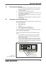
• At the top part of the cabinet, the Calculation Unit is
placed. It contains the boards for processing and calcu-
lating the measured values. It also contains the Backup
Display with a keyboard. The Backup Display is used
mainly for service purposes.
A Level Unit can connect up to 30 Transmitters. In large
systems with more than 30 tanks, a Slave LU cabinet is used.
With a Slave LU, up to 30 additional tanks can be connected.
The Slave Level Unit does not contain any Calculation Unit
since the signals from it are processed in the main Level Unit.
1
0
F1
2A
F2
1A
F3
2A
F4
2A
F5
1A
F6
2A
NEMKO Nr Ex 94C346 (EEx ia)IIC
SERVICE PC
CONNECTOR
F8-8A
F7-2A
(SERVICE POWER)
SERVICE
POWER
S1
LP Power Block
9150 064-641
POWER SUPPLY
115 VAC
230 VAC
F1-F6= LI Power Fuses.
WARNING: Any substitution
of components may impair
intrinsic safety. See Service
Manual.
OPEN HERE
A
PORT 1
B
CENT 1
C
STBD 1
1
PORT 2
CENT 2
STBD 2
PORT 3
CENT 3
STBD 3
PORT 4
CENT 4
STBD 4
PORT 5
CENT 5
STBD 5
2 3 4 5
POWER SUPPLY
A
PORT 1
B
CENT 1
C
STBD 1
1
PORT 2
CENT 2
STBD 2
PORT 3
CENT 3
STBD 3
PORT 4
CENT 4
STBD 4
PORT 5
CENT 5
STBD 5
2 3 4 5
POWER SUPPLY
NEMKO Nr. Ex 94C346(Exia)IIC
Transmitter Cable Data:
Lmax=500 µH, Cmax=100 µF
POWER SUPPLY
GROUND
FAILURE
NEMKO Nr. Ex 94C346(Exia)IIC
Transmitter Cable Data:
Lmax=500 µH, Cmax=100 µF
GROUND
FAILURE
7 8 9 0
4 5 6
1 2 3
ALARM
SYSTEM
MENU
SERV
ENTER
CLEAR
OK i
1 2 3
LCP LCM
LCS
LCM
LCS
LCI
Calculation Unit
Transmitter Interfaces
Power Block
Figure 5-1. Level Unit.