


81
Service Manual
Third edition, June 1997
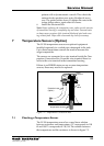
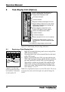
Note: The sensor must be fitted to the vent hole by means of a
Nylon hose.
Note: Make a note of how the leads are connected to the wire
terminal on the Electronic Box before you disconnect the leads.
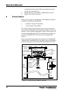
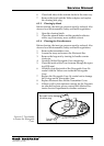
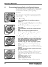
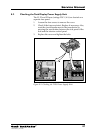
6.4.1 Cleaning the Inert Gas Pressure Sensor
Follow the steps below when cleaning the IG pressure sen-
sor:
1. Open the cover to the transmitter housing.
2. Disconnect the leads to the IG-sensor and remove the
sensor.
3. Remove the sensor and the nipple.
4. Do not attempt to clean the sensor itself as it can easily
be damaged. Clean the nipple and the screw in the
mounting assembly as well as the opening in the bot-
tom of the Transmitter housing or into the Waveguide
Cone.
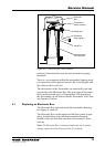
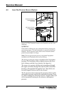
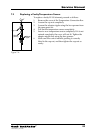
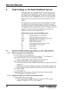
6.4.2 Replacing the Inert Gas Pressure Sensor
Follow steps 1-3 above (chapter 6.3.1) to remove the sensor.
Follow the steps below when replacing the IG pressure
sensor:
1. Install the new sensor in the same way as the one you
have just removed. Original or new gaskets must be
used.
2. On Parabolic Antenna: Tighten screw through the
banjo nipple to 75 Nm (55 lbsft) torque.
On Cone Antenna: Tighten cap nut to 55 Nm (40 lbsft)
torque.
3. Be sure to connect the electrical leads and the vent hose
in the same way as before. The vent hose must not be
folded or squeezed.
Note: A zero pressure calibration of the IG pressure sensor must be
done when it has been replaced.
6.4.3 Zero Pressure Calibration of IG Pressure Sensor
Make sure that the tank is ventilated and that it has atmo-
spheric pressure. Be aware that a strong wind into a tank
opening can change the pressure inside the tank quite con-
siderably.
Read chapter 3.28 “IG Pressure Zero Adjust” for a descrip-
tion of how to adjust the IG pressure sensors.