


71
Service Manual
Third edition, June 1997
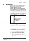
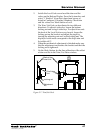
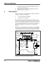
One Transmitter Interface is connected to the Calculation
Unit at the top of the Level Unit, while the other Transmitter
Interfaces are connected in serial with a flat cable between
each one.
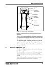
5.10.3 Power supply to the Transmitter Interface
The intrinsically safe parts of the Transmitter Interfaces
receive power from the Power Block at the bottom of the
Level Unit via separate cables. The non-intrinsically safe
parts receive their power from the Calculation Unit power
supply.
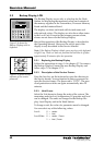
5.10.4 Ground Failure Indication
On the front panel of the Transmitter Interface there is a LED
indicating any ground failure on the intrinsically safe equip-
ment connected to it.
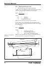
5.10.5 Addressing the Transmitter Interface
There is an address switch on side of the Transmitter Inter-
face. When replacing a Transmitter Interface, it is important
to set the address switch in the same way as on the one that
is replaced.
Switches 1 and 2 are used for setting the address of up to
four Transmitter Interfaces in the system. Switches 3 and 4
are used to select the LCM that handles the Transmitter
Interface.
Switch 1 Switch 2 LI number Transmitters
ON ON LI no. 1
OFF ON LI no. 2
ON OFF LI no. 3
OFF OFF LI no. 4
Switch 3 Switch 4 LCM configuration
OFF ON Only LCM 1
ON OFF Only LCM 2
OFF OFF Both LCM 1 and 2 in
redundancy mode
As default the switch is set to LI no 1 and for only LCM 1
(Switch 1=ON, 2=ON, 3=OFF, 4=ON)
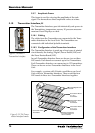
5.10.6 The Analog/Digital/Power Board (LIA)
The Analog/Digital/Power Board;
- relays the analog signal from the Transmitter to the
Signal Board,