


63
Service Manual
Third edition, June 1997
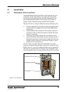
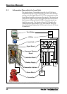
5.7 Interface Board, LCI
The Interface Board works as an interface between the Pro-
cessor Memory Board and the Work Station. It also supports
the Backup Display with its keyboard. If a service PC is
connected, it communicates via this board.
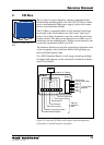
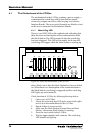
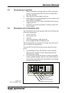
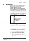
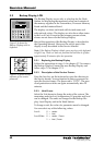
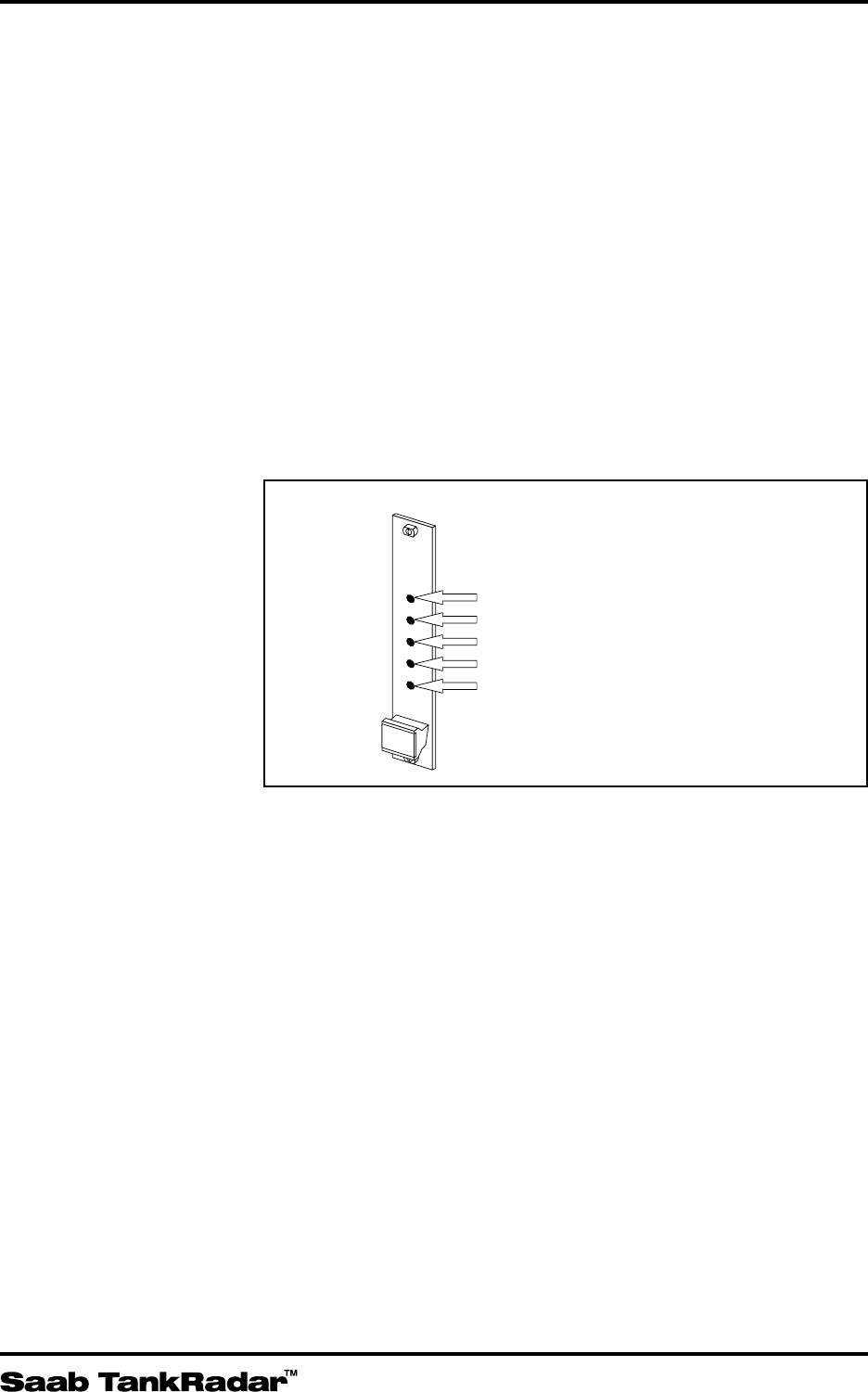
The Interface Board has five LEDs on the front panel. The
first LED from the top indicates the transmitted communica-
tion with the Work Station, normally through the RS 485
Interface Board in the I/O Box (position Com 4). The second
LED indicates the received signals from the Work Station. In
a similar way, the third and fourth LEDs show the communi-
cation with a service PC, if one is connected to the spare RS-
232 port on the Level Unit. The fifth LED shows if the watch
dog has been triggered since the LU was last restarted.
Send to Work Station
Receive from Work Station
Send to Service PC
Receive from Service PC
Watch Dog
LCI
Figure 5-5. LEDs on the
Interface Board.
5.7.1 Troubleshooting the LCI
The LEDs are useful when troubleshooting the system. If the
top LED (LCI transmit) is flashing the LCI is probably OK.
See fault finding chapter 9.1.1.
If the top LED (LCI transmit) is not flashing while the second
LED from top (LCI receive) is flashing or if none of these
LEDs are flashing, the LCI may not be functioning. Follow
the steps below:
1. Check cables and connectors between LU and I/O Box
as well as between I/O Box and Work Station.
2. Check that correct baud rate is used on both Work
Station and LCI. See chapter 3.18 for more information.
3. If no fault is found, replace the LCI board. It is included
in the Complete Spare Parts set. See instructions in
chapter 5.7.2 below.