


72
Service Manual
Third edition, June 1997
- relays the digital signals between the Transmitter and
the Processor Memory Board and
- stabilizes the intrinsically safe power supply and checks
for ground failure.
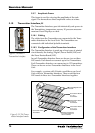
5.10.7 The Zener Barrier Board (LIZ)
The Zener Barrier Board has five separate circuits for the
intrinsically safe connection of up to five Transmitters. Each
of the five separate circuits on the Zener Barrier Board con-
tain four zener barriers.
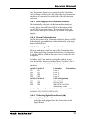
The Zener Barrier Boards are connected to the Analog/
Digital/Power Board (LIA) with flat cables. The Transmitters
are connected to the Zener Barrier Board with jackable con-
nectors with eight conductors, from four twisted pair cables.
Note: The fuses on the LIZ must not be changed in the field. If a
LIZ has a broken fuse, the whole board must be changed as a com-
plete unit.
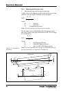
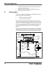
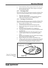
5.10.8 Removing a Transmitter Interface (LI)
1. If they are not marked, mark up all the connectors so
that they can be easily replaced in the same positions.
2. Remove all the transmitter connectors.
3. Remove the power supply connector and the flat cable
connector (or connectors, if more than one LI is used).
4. Loosen the four nuts and remove the LI.
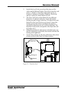
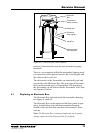
5.10.9 Replacing a LIZ or a LIA
To open the LI, a TORX-screwdriver is required. This screw-
driver can be found in the Complete Spare Part set or it is
included together with the spare LIZ or LIA.
1. Remove the LI according to steps 1-4 in chapter 5.10.8
above.
2. Look for an “Open here”-arrow on the front of the LI
and remove that end wall.
3. Slide the boards out a little bit so that you can remove
the connector to the board you need to replace. Slide it
out carefully.
4. Carefully slide the new board into the LI. Mount the
end wall.
5. If it was an LIA that was replaced, set the address
switches to same positions as on the one you replaced.
6. Mount the LI according to the instructions in chapter
5.10.10.