


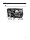

Start-Up/Operation
Operating Displays
84 HercuLine™ 2000 Series Actuator - Installation, Operation and Maintenance Manual Revision 7
7/08
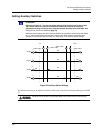
Operating Displays
Pressing the DISPLAY key cycles the display through a number of operating parameters. Table 34 shows a
number of sample displays that can be shown during operation.
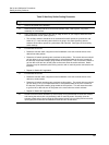
Table 34 Typical Operating Displays
Display Description
0.0
INP
Input
— Upper Display = Shows input value
Lower Display = prompt
00
OP 0.5
Output— Upper Display = Shows input value
Lower Display = Shows output value
100.0
DE 99.9
Deviation
— Upper Display = Shows input value
Lower Display = Shows value of deviation of
sensor from input.
0.6
POS
Position— Upper Display = Shows value of position sensor.
Lower Display = prompt
NOTE: Position display will show negative values, if appropriate.
NOTE: When the AUTO/MANUAL key is pressed, placing the actuator in manual mode, the local display
mode is forced to the Position display (POS). The Manual L.E.D. indicator should be lit. When the
AUTO/MANUAL key is pressed again, placing the actuator in auto mode, the local display mode is forced to
the Output display (OP). The Auto L.E.D. indicator should be lit. Set up parameters can still be accessed.
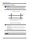
Motor Stall
The actuator is equipped with a low current motor that prevents against burnout if the motor becomes stalled. A
stall condition occurs when the motor position does not follow the input, or if the motor does not reach setpoint
within a given period of time.
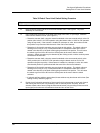
When the stall condition occurs, a stall alarm is indicated. The actuator sets the STALLED LED indicator ON
and also any other alarms or relay contacts that are programmed to close whenever a stall condition is detected.
The motor drive for the indicated direction is shut off approximately 3 minutes after the stall alarm is indicated.
Also, the appropriate CW/CCW LED direction indicator is turned OFF.
The maintenance statistic for accumulated stall time gets updated during the stalled condition.
To reactivate the drive in the stalled direction, change the position of the drive to the opposite direction and set
at a point below where the stall originally occurred, then start the drive in the stalled direction.
Note: A stall condition is not detected if a limit end of travel limit switch is activated while the motor is moving
toward the setpoint, or if the motor position is within 0.5% of calibrated motor 0% and 100% end points.”