


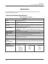

Specifications
Technical and Operating Specifications
6 HercuLine™ 2000 Series Actuator - Installation, Operation and Maintenance Manual Revision 7
7/08
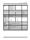
Electrical
Mains Supply
100-130 Vac single phase, 50 Hz or 60 Hz
200-240 Vac single phase, 50 Hz or 60 Hz
Motor
Instant start/stop, non-coasting, non-burnout, continuous duty, permanent
magnet, synchronous induction motor. Can be stalled up to 100 hours without
damage.
Motor Current
= No load = full load = locked rotor = 0.4 amp for 120Vac, 0.2 amp for 240 Vac
Loss of Power
Stays in place on loss of power
Local Auto/Manual Switch
Optional – Allows local and automatic operation of the actuator.
End of travel Limit
Switches
Standard – adjustable to limit actuator travel to less than 90 or 150 degrees
respectively
Auxiliary Switches/Relays
Optional – Up to 4 additional SPDT switches rated at (10 A at 125 Vac, 5 A at 250
Vac).
Certifications
Approvals
CSA/UL (Standard)
CE Compliant (optional)
Enclosure Rating
Type 4 (NEMA 4), IP66 (standard)
Torque Settings of Crank Arm Bolts
Clamp Bolt
88 lb-in (10 N-m)
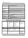
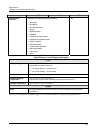
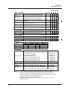
Electrical and Performance Specifications
HercuLine
®
2002 HercuLine
®
2001 HercuLine
®
2000/2003
Input Signals
Analog:
• 0/4 to 20 mA (With CPU
PWA jumper in current
position)
• 0/1 to 5 Vdc
• 0 to 10 Vdc
Digital:
• Modbus RTU (RS485)
Analog:
• 0/4 to 20 mA (With CPU
PWA jumper in current
position)
• 0/1 to 5 Vdc
• 0 to 10 Vdc
• Series 90 control
Digital:
• Modbus RTU (RS485)
120 vac drive open/120 vac
drive close
240 vac drive open/240 vac
drive close
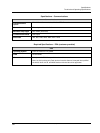
Isolation
Input signal, output signal and power are isolated from each other. NA
Load Requirement (4-20)
Current Out — 0 to 1000 ohms NA
Input Impedance
0/4 to 20 mA
0/1 to 5 Vdc
0-10 vdc
250 ohms
10 K ohms
NA
Feedback
0 to 20 mA, 4 to 20 mA
0 to 5 Vdc & 1 to 5 Vdc with 250 ohm resistor, (0 to 16 Vdc with 800
ohm resistor)
Dual output 1000 ohms
over 90 degrees (135 ohms
with 158 resistor)
Dual output 1000 ohms
over 150 degrees (135
ohms with with 158 resistor)