


Burner Control/Flame Safety
Split Range
26 HercuLine™ 2000 Series Actuator - Installation, Operation and Maintenance Manual Revision 7
7/08
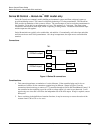
Split Range
The HercuLine
®
2001/2002 actuators can be set up to operate within a narrow input range (for example,
4 to 12mA input) in certain applications. The procedure in
Table 5 describes how to set up an actuator
to operate as part of a split valve configuration.
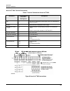
Table 5 Split Range Set Up Procedure
Step Action
To Set Actuator span to operate from 4 to 12 mA input.
1 Enter Set Up mode by pressing SET UP key
2 Select SET INPUT group
3 Press FUNCTION key until INP HI (on lower display) is selected.
4 Set INP HI value to 50.0
5 Press FUNCTION key to select INP LO and set value to 0.0
6 Press DISPLAY key to exit Set Up mode.
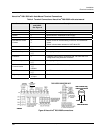
To Set Actuator span to operate from 12 to 20 mA input.
1 Enter Set Up mode by pressing SET UP key
2 Select SET INPUT group
3 Press FUNCTION key until INP HI (on lower display) is selected.
4 Set INP HI value to 100.0
5 Press FUNCTION key to select INP LO and set value to 50.0
6 Press DISPLAY key to exit Set Up mode.
ATTENTION
Be sure to review failsafe strategy for your process application.
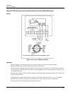
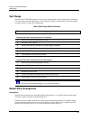
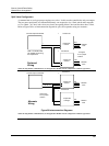
Master/Slave Arrangement
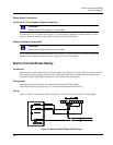
Introduction
With the motor positioner, the controlling signal for the actuator is a 4 to 20mA from a current output
controller as shown in the flow diagram in
Figure 16.
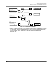
Unlike the position output controller, the current output controller must produce a continuous analog
signal or the actuator will revert to one of its failsafe states. Signal failure is not a problem since the
available failsafe settings allow you to set the actuator position on signal loss.