


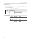
Set Up and Calibration Procedures
Calibration
68 HercuLine™ 2000 Series Actuator - Installation, Operation and Maintenance Manual Revision 7
7/08
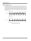
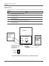
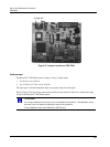
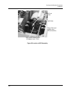
Jumper W2
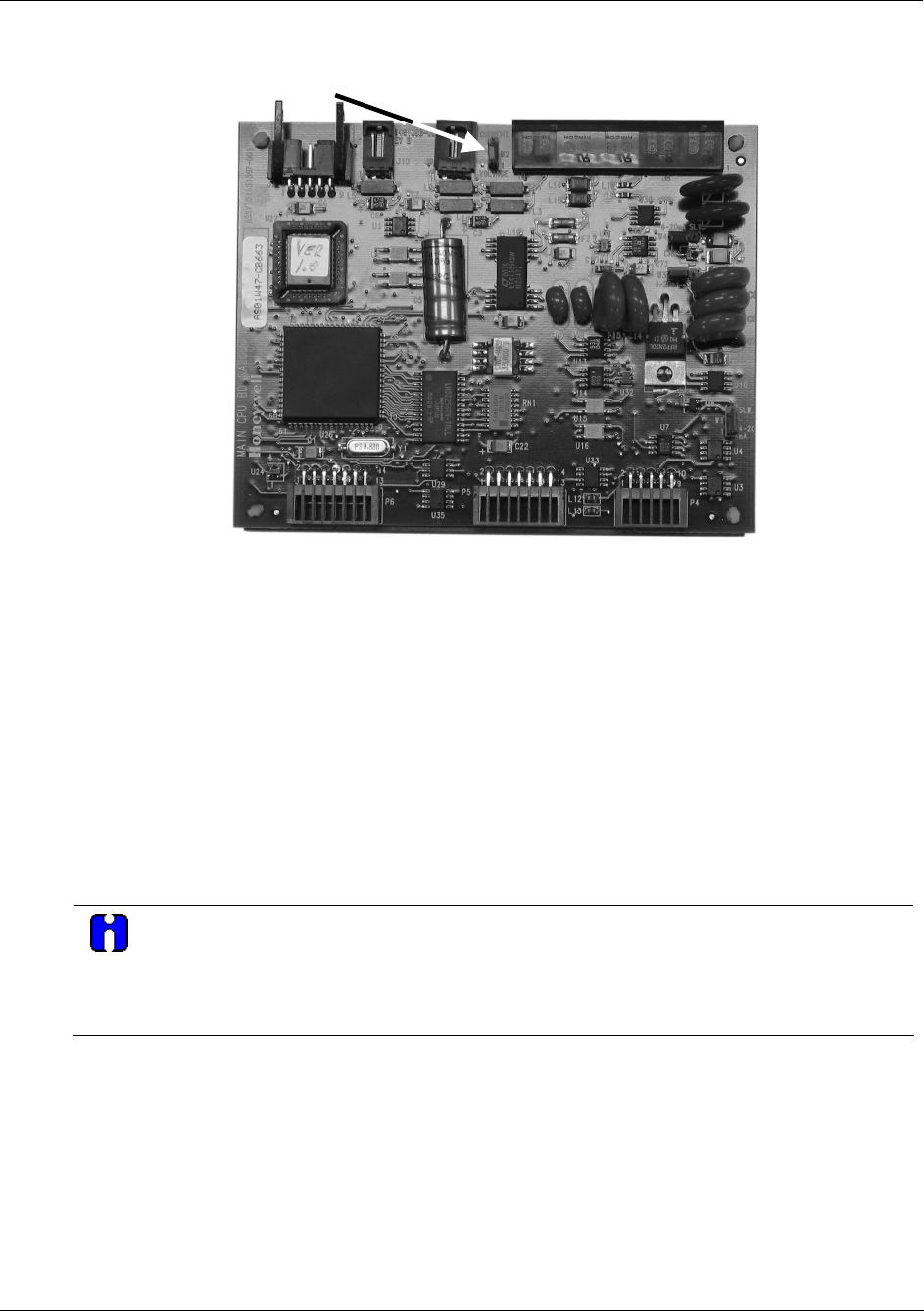
Figure 27 Jumper Location on CPU PWA
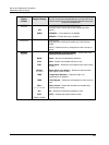
Calibrate Input
The HercuLine
®
2001/2002 actuator accepts a variety of signal inputs.
1.
0 to 20 mA, or 4 to 20 mA
2.
0 to 5 Volts,1 to 5 Volts, or 0 to 10 Volts
The input type is selected through the Input set up group using the local keypad.
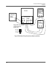
Refer to
Figure 25 for the wiring connections and follow the procedure in Table 25 to calibrate the input
circuit of the HercuLine
®
2001/2002 actuator.
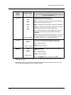
ATTENTION
For an input calibration to be saved, you must complete the procedure. The calibration will not
be saved if you exit without completing the steps of the procedure.
To exit calibation mode, press DISPLAY or SETUP keys.