


Set Up and Calibration Procedures
Relays Set Up Group
44 HercuLine™ 2000 Series Actuator - Installation, Operation and Maintenance Manual Revision 7
7/08
Relays Set Up Group
ATTENTION
The Relay set up group parameters are accessible only if relay PWAs are installed in the
actuator. HercuLine
®
2001 actuators can be equipped with one PWA –for a total of two SPDT
relays. Using the Relay set up groups you can program the installed relays to operate in
response to various operating conditions.
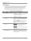
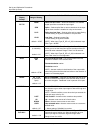
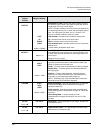
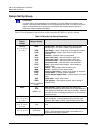
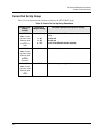
Table 13 lists the parameters and selections available when the SET RELAYn group is selected.
Table 13 Relay Set Up Group Parameters
Actuator Lower
Display
Prompt
Selections or
Range of Setting
Parameter Definition/PDA HercuLink
®
Prompt
RTYPny
n = 1, 2, 3, or 4
y = 1 or 2
NONE
InPR
PosR
DEV
ULim
LLim
T Hi
T Lo
STRT
STAL
MAN
PWRF
FsFA
PosF
DiGI
TDEG
default = InPR and
NONE
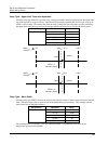
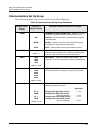
RELAY TYPE— Selects the relay number and the relay
activation type. See
Table 14 Relay Type Descriptions.
Input Range— Upper / lower limits of input signal exceeded
Position Range— Upper / lower limits of motor position
exceeded
Deviation— Deviation from input exceeded
Upper Limit Travel— Same as PosR for upper limit
Lower Limit Travel— Same as PosR for lower limit
Temperature High— High temperature limit exceeded
Temperature Low— Low temperature limit exceeded
Starts— Motor starts limit exceeded. Allows setting of
multiplier value.
Stalled— Motor position does not follow input
Manual— Actuator is set to manual mode
Power Up Test Failure— Failure of any power up diagnostic
Failsafe Alarm— Failsafe condition detected
Position Sensor Signal Failure— position output out of valid
range
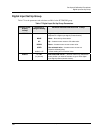
Digital Input— Digital input closure
Total Degrees— total degrees traveled. Allows setting of
multiplier value.
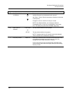
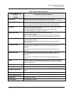
RnyE*
X1
X10k
default = X1
MULTIPLIER— (Relay Types STRT and TDEG only)
Selects the multiplier for the number limit of motor starts and
total degrees traveled before the relay is activated. Multiplier
specifies the value on display as times one (X1) or times ten
thousand (X10k).
RnyVAL
n = 1, 2, 3, or 4
y = 1 or 2
0.0 to 100.0
RELAY VALUE— Sets numerical value of limit where relay
trips (energizes). Units are determined by the relay type
selection. See
Table 14 Relay Type Descriptions for units.
Rny HL
n = 1, 2, 3, or 4
y = 1 or 2
HI
LO
RELAY HIGH/LOW— Sets relay trip point to high or low
limit.
RLYnHY
n = 1, 2, 3, or 4
0.0 to 100.0
(in percent)
RELAY HYSTERESIS— 0.0 to 100.0% of span or full output.
NOTE: Relay Hysteresis parameter is accessible only if
appropriate relay type is selected.
n is the relay number, y is the relay contact.