


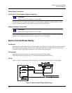

Burner Control/Flame Safety
Master/Slave Arrangement
Revision 7 HercuLine™ 2000 Series Actuator - Installation, Operation and Maintenance Manual 27
7/08
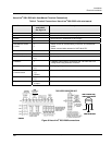
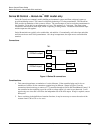
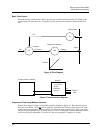
Basic Flow Control
When the process variable signal is below set point, the controller increases current (4 to 20mA) to the
actuator input and opens the valve. Controller set point governs valve position to obtain desired flow
rate.
PV
SP
4 to 20 mA
Controller
Positioner & Actuator
Linkage
Position
mA
Valve
Orifice Plate
FIC
MP
FT
Figure 16 Flow Diagram
Hot
Actuator
Neutral
Ground
120/240
VAC
250 Ohms
1 to 5 VDC
+
-
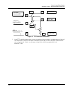
Current Output Controller
4 to 20 mA
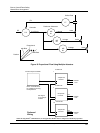
Figure 17 Interconnection Diagram
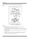
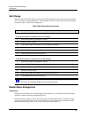
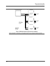
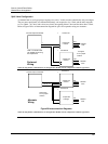
Proportional Flow using Multiple Actuators
Refer to flow diagram in
Figure 18 and interconnection diagrams in Figure 19. The controller governs
flow rate in one burner. Only that
flow is measured. Since #2 and #3 motor positions receive the same
signal as #1 motor positioned, valves #2 and #3 will deliver the same amount of fuel. This is true when
the span and zero adjustment are all set the same as in curve 2 of the graph. Other relationships between
units exist if the span adjustment (3) for ratio or if the zero adjustment is changed (1) for bias.
Jumper W2
= Current
See Figure
27 for jumper
location