


Set Up and Calibration Procedures
Drive Set Up Group
56 HercuLine™ 2000 Series Actuator - Installation, Operation and Maintenance Manual Revision 7
7/08
Drive Set Up Group
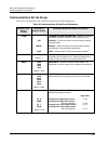
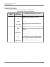
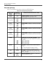
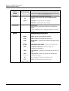
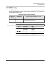
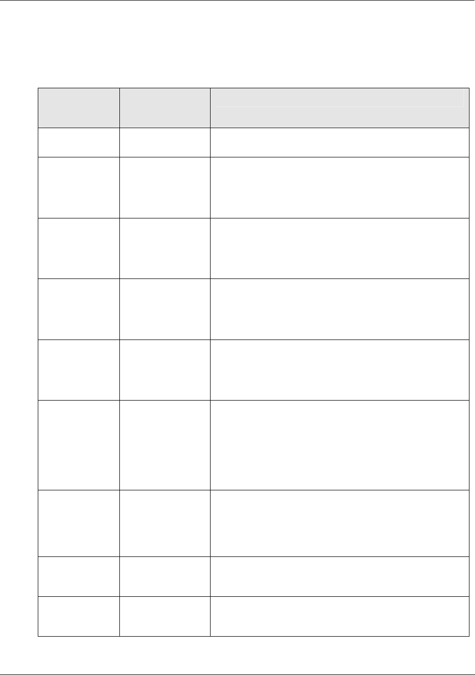
Table 21 lists the parameters and selections available for the SET DRVINF group.
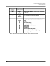
Table 21 Drive Set Up Group Parameters
Actuator Lower
Display
Prompt
Selections or
Range of Setting
Parameter Definition/PDA HercuLink
®
Prompt
VERSON
nnnn FIRMWARE VERSION
— Read Only. Displays the firmware
version currently in use by the actuator’s CPU.
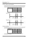
SPEED
(150° @ 60hz)
6 S
12 S
25 S
50 S
75 S
STROKE SPEED
— Read Only. The speed is the number of
seconds it takes for the actuator shaft to move its full range
of travel.
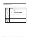
SPEED
(90° @ 60hz)
3.2 S
7.2 S
15 S
30 S
45 S
STROKE SPEED
— Read Only. The speed is the number of
seconds it takes for the actuator shaft to move its full range
of travel.
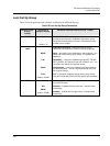
SPEED
(150° @ 50hz)
7.5 S
15 S
30 S
60 S
90 S
STROKE SPEED
— Read Only. The speed is the number of
seconds it takes for the actuator shaft to move its full range
of travel.
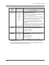
SPEED
(90° @ 50hz)
4.5 S
9 S
18 S
36 S
54 S
STROKE SPEED— Read Only. The speed is the number of
seconds it takes for the actuator shaft to move its full range
of travel.
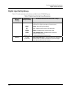
POWER
1206
1205
2206
2205
POWER INPUT VOLTAGE AND FREQUENCY
— Read
Only. Selects the power input voltage and line frequency of
the actuator.
1206— 120Volts, 60Hz
1205— 120Volts, 50Hz
2206— 220Volts, 60Hz
2205— 220Volts, 50Hz
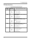
ROTATE
90
150
ROTATION
— Indicates the factory calibrated degrees of
rotation.
90— Factory calibrated for 90 degrees of rotation.
150— Factory calibrated for 150 degrees of rotation.
TAG
nnnnnn TAG NAME
— Selects the tag name or identifier of the
actuator. Up to 6 alphanumeric characters. See “Set Tag
Name” on next page.
DMFG
mmddyy *
or
ddmmyy
MANUFACTURING DATE— Read Only. Displays date
code of manufacture for actuator.