


Set Up and Calibration Procedures
Calibration
Revision 7 HercuLine™ 2000 Series Actuator - Installation, Operation and Maintenance Manual 65
7/08
Calibration
Calibration of the HercuLine
®
2000 Series Actuator may consist of calibrating the motor circuit that
positions the actuator with 0/4-20mA input signal, calibrating the potentiometer or non-contact sensor, and
calibrating the slidewire emulation output or the 0/4-20mA output signal. Typically, only a motor
calibration is required for installation.
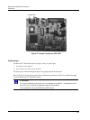
Calibration is performed by connecting test equipment to the input terminals or output terminals and then
using the keypad and display to step through the calibration group functions.
ATTENTION
Input calibration and output calibrations are performed at the factory and may not be
necessary. Normally, you may only need to perform Calibrate Motor.
Only qualified personnel should perform calibration.
High voltages exist inside the actuator case. Do not touch the powered wires inside.
Death or serious injury can occur.
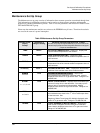
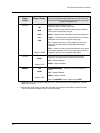
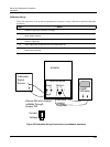
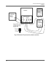
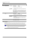
Equipment Needed
The table below lists the equipment you will need to calibrate the HercuLine
®
2000 input and output
circuits.
Procedure Equipment Needed
Input Calibration
• A calibrated signal source which can provide current (4 to 20
mA) or voltage (0 to 10 V) with an accuracy of 0.02% or better.
• Two insulated copper leads for connecting the current source
to the actuator.
Output Calibration
• A digital voltmeter with an accuracy of 0.01% or better.
• A 250 ohm resistor 0.01% tolerance.