


Set Up and Calibration Procedures
Overview
Revision 7 HercuLine™ 2000 Series Actuator - Installation, Operation and Maintenance Manual 31
7/08
Set Up and Calibration Procedures
Overview
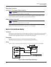
Once you have installed the actuator, you can verify, set or change certain operating parameters. Set up is
accomplished through use of the local display and keypad interface through your PDA with HercuLink
®
software (see HercuLink
®
manual 62-86-25-11) or via the HART
®
communication option. Please keep in
mind that the unit is calibrated at the factory for your application and can be placed into service right out of
the box. Changing operating parameters may require recalibration of the actuator. This section details the
various operating parameters and functions of the actuator available using the local display and keypad
interface, and calibration procedures.
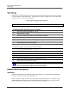
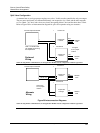
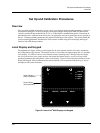
Local Display and Keypad
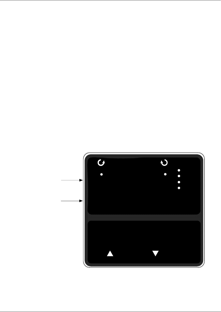
The alphanumeric display and keys on the keypad are the local operator interface for control, monitoring,
and configuration of the actuator. The display consists of a four character upper display and a six character
lower display. Six LEDs of various colors indicate actuator-operating status. Directly below the display
are six keys that allow you to setup, monitor, and control the actuator locally, as well as call up various
operating parameters and configuration values on the display.
Figure 21 shows the physical features of the
display and keypad.
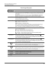
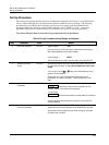
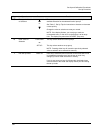
Table 6 summarizes the various functions you can perform using the keys as well as
descriptions of the status indicators.
DISPLAY
MAN/AUTO
FUNCTIONSET UP
STALLED
ALARM
MANUAL
AUTO
Upper Display
(Four Characters)
Lower Display
(Six Characters)
Figure 21 HercuLine
®
2000 Display and Keypad