


Set Up and Calibration Procedures
Calibration
Revision 7 HercuLine™ 2000 Series Actuator - Installation, Operation and Maintenance Manual 71
7/08
Calibrate Output
HercuLine
®
2001/2002 actuator can be one of three output types:
1.
0 to 20 mA, or 4 to 20 mA output
2.
0 to 5 Volts, or 1 to 5 Volts with 250 ohm range resistor
3.
Slidewire emulation.
The output signal range is selected through the Current Out set up group using the keypad and local
display.
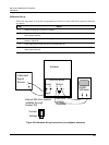
0/4-20 mA Output
The HercuLine
®
2001/2002 Actuator comes already calibrated from the factory. If it becomes necessary to
do a calibration in the field, adjust the output using the procedure in
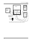
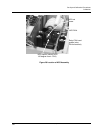
Table 27. Refer to Figure 25 for a
diagram to connect a signal source to the actuator input and a DVM to measure actuator output signal.
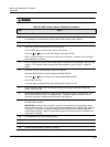
This procedure provides the steps to calibrate the actuator for a 4 to 20mA output. If you are using another
output type, change the procedure accordingly.
ATTENTION
For an output calibration to be saved, you must complete the procedure. The calibration will
not be saved if you exit without completing the steps of the procedure.
To exit calibation mode, press DISPLAY or SETUP keys.
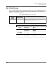
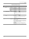
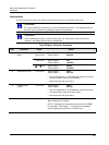
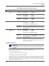
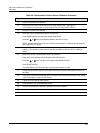
Table 27 Output Calibration Procedure
Step Operation Press Result
1
Enter Calibration
Mode
SETUP
until you see
Upper Display =
CAL
Lower Display =
CUR OUT
FUNCTION Upper Display = DIS
Lower Display =
CALOUT
or key
Upper Display =
BEGN
Lower Display =
CALOUT