


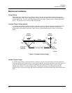
Installation
Electrical Installation
Revision 7 HercuLine™ 2000 Series Actuator - Installation, Operation and Maintenance Manual 19
7/08
HercuLine
®
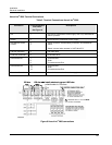
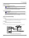
2001/2002 with Auto/Manual Terminal Connections
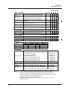
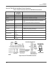
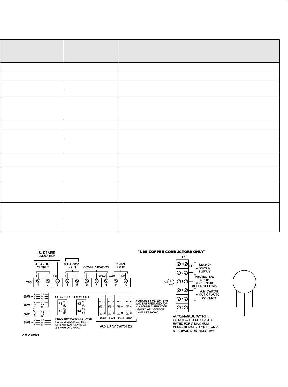
Table 4 Terminal Connections: HercuLine
®
2001/2002 with auto/manual
Connection
Terminal Numbers
and LABEL
See Figure 9
Descriptions
TB1
Hot 1 Hot wire for 120/240VAC mains supply
Neutral 2 Neutral wire for 120/240VAC mains supply
Protective Ground 3 Ground wire connection for mains supply
Auto/Manual Switch
Contact
4
5
Switch contact to indicate setting of actuator AUTO/MANUAL
switch.
Switch is closed when actuator is “NOT-IN-AUTO”
6
TB3
4 to 20mA Output*
1 (+)
2 (-)
Analog signal output
Feedback 3
Feedback signal used in conjunction with 4 to 20mA OUTPUT
voltage when using Slidewire Emulation
4 to 20mA Input
4 (+)
5 (-)
Analog signal input
Modbus
Communication
6 (+)
7 (-)
8 Shield
Connection for RS485 Modbus loop wires
HART Communications
4 (+)
5 (-)
HART Communication is 4-20 mA only.
Digital Input
9 Com
10 Input
Customer’s contact closure
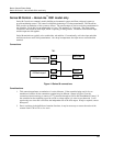
Auxiliary
Connector
_
Brown
Black
Blue
+
Black Wire Not Used
HART connection using
external Turck connector
+
_
HART
Communications
Connection
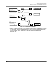
Auxiliary
Connector
_
Brown
Black
Blue
+
Black Wire Not Used
HART connection using
external Turck connector
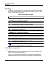
Auxiliary
Connector
_
Brown
Black
Blue
+
Black Wire Not Used
HART connection using
external Turck connector
+
_
HART
Communications
Connection
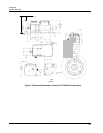
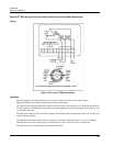
Figure 9 HercuLine
®
2001/2002 connections