Installation
Before Starting
Revision 7 HercuLine™ 2000 Series Actuator - Installation, Operation and Maintenance Manual 13
7/08
Before Starting
Unpacking
If there are visible signs of damage to the shipping container, notify the carrier and Honeywell immediately.
If there is no visible damage, compare the contents with the packing list. Notify the carrier and Honeywell
immediately if there is equipment damage or shortage.
Please do not return goods without contacting Honeywell Applications Center in advance. The contact number
is 1-800-423-9883.
Installation Considerations
Mount the actuator in a location where it will be easily accessible for maintenance and for manual operation by
means of the handwheel. The exact location must be determined in accordance with the linkage used.
It is important that the actuator be mounted securely to a solid foundation commensurate with the maximum
torque developed. Use studs or bolts that are as large as the foot mounting holes.
Allocate sufficient clearance around the actuator for the removal of all covers to permit inspection of internal
parts and to provide access to the handwheel.
Actuator Mounting
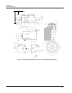
Firmly bolt the actuator to a mounting surface that will not distort when subjected to the torque stresses
generated by the actuator. The output shaft of the actuator should be parallel to the output shaft of the driven
device. The output shaft crank arm is fully adjustable through 360°.
Mounting holes (bottom and side) and location of shaft/crank arm duplicate mounting for Honeywell
Actionators M640A, 740A, 940A for drop-in replacement. Optional adaptor plates available for replacing
Landis and Staefa SQM53/56 and Barber Coleman series MP495 models.


