


Set Up and Calibration Procedures
Calibration
Revision 7 HercuLine™ 2000 Series Actuator - Installation, Operation and Maintenance Manual 73
7/08
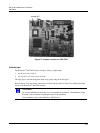
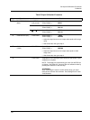
Table 28 Slidewire Emulation Calibration Procedure
Step Operation Press Result
1
Enter Calibration
Mode
SETUP
until you see
Upper Display =
CAL
Lower Display =
OUTPUT
FUNCTION Upper Display = DIS
Lower Display =
CALOUT
or key
Upper Display =
BEGN
Lower Display =
CALOUT
2 Calibrate Zero (0%) FUNCTION Upper Display = xxx
Lower Display =
ZERO
xxx = arbitrary number assigned by software
or key
Adjust actuator output voltage using down key until value on
DVM ceases to change, then press up key until value on DVM
moves up one digit
3
Calibrate Span
(100%)
FUNCTION Upper Display =
xxxx
Lower Display =
SPAN
xxx = arbitrary number assigned by software
or key
Adjust actuator output voltage using
key until value on DVM
ceases to change, then press
down key until value on DVM
moves down one digit
FUNCTION Calibration for zero and span output values are now stored.
Slidewire Emulation Output Calibration is complete. Read meter
connected to actuator output.
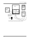
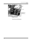
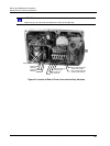
Calibrate Position Sensor
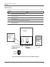
ATTENTION
The Position Sensor is factory calibrated. Under normal operation it does not require
calibration.
Sensor calibration may be necessary due to any of the following conditions:
• The sensor output is incorrect,
• The position sensor in the actuator has been replaced,
• The position sensor adjustment has been disturbed.
When the position sensor has been replaced (or serviced), you should perform a calibration of the position
sensor circuit and then store it as the motor factory calibration. Please note that performing this procedure
will destroy any previously stored motor factory calibration values.
Table 29 outlines the steps to perform a
calibration to the position sensor circuit.