


Installation
Electrical Installation
22 HercuLine™ 2000 Series Actuator - Installation, Operation and Maintenance Manual Revision 7
7/08
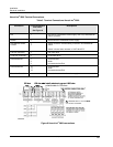
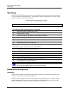
Step Action
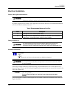
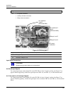
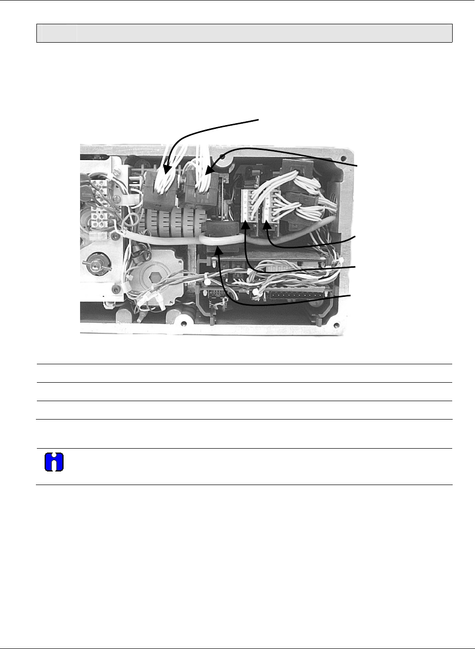
8 • AC power connection
• Auxiliary switches connection
• Relay contact connection
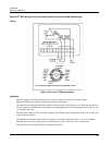
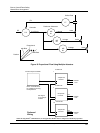
Relays 3 and 4
Relays 1 and 2
Aux switches
1 and 2
(SW3 and SW4)
Aux switches 3
and 4
(SW5 and SW6)
AC power
connection
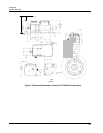
Figure 12 CE Wiring part 2
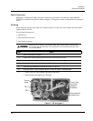
9 Install new gasket and top cover. Secure top cover with 6 captive screws.
10 Reapply AC power to the actuator.
11 Actuator is ready for use.
Input Signal Connections
ATTENTION
Shielded and grounded cables are recommended.
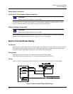
0/4-20 mA Input Signals
For current signal input, ensure jumper W2 on the CPU PWA is in the “Current” position. See
Figure 27 on
page
68. Observing polarity, connect the signal input wires TB3–4(+) and TB3–5(-) on CPU terminal board.
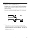
0/1-5 Vdc and 0 to 10 Vdc Input Signals
For voltage signal input, ensure jumper W2 on the CPU PWA is in the “Voltage” position. See
Figure 27 on
page
68. Observing polarity, connect the signal input wires to terminals TB3–4(+) and TB3–5(-) of the terminal
block.