


Contents
viii HercuLine™ 2000 Series Actuator - Installation, Operation and Maintenance Manual Revision 7
7/08
Figures
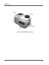
Figure 1 HercuLine
®
2000 Series Actuator 2
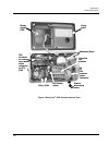
Figure 2 HercuLine
®
2002 Actuator Internal View 3
Figure 3 Outline and Dimensions of HercuLine
®
2000 Series Actuators 14
Figure 4 Constant Torque Linkage 15
Figure 5 Variable Torque Linkage 16
Figure 6 Standard crank arm 16
Figure 7 Crank arm with optional ball joint and push rod 16
Figure 8 HercuLine
®
2000 connections 18
Figure 9 HercuLine
®
2001/2002 connections 19
Figure 10 HercuLine
®
2003 connections 20
Figure 11 CE wiring part 1 21
Figure 12 CE Wiring part 2 22
Figure 13 Burner Control/Flame Safety Wiring 23
Figure 14 Series 90 connections 24
Figure 15 T775 Controller connections 25
Figure 16 Flow Diagram 27
Figure 17 Interconnection Diagram 27
Figure 18 Proportional Flow Using Multiple Actuators 28
Figure 19 Multiple Actuator Interconnection Diagrams 29
Figure 20 Interconnection Diagrams 30
Figure 21 HercuLine
®
2000 Display and Keypad 31
Figure 22 Relay connectors 46
Figure 23 Regions of Motor Travel 62
Figure 24 Auto - Manual Switch 64
Figure 25 Calibration Wiring Connections (non-slidewire emulation) 66
Figure 26 Calibration Wiring Connections (slidewire emulation) 67
Figure 27 Jumper Location on CPU PWA 68
Figure 28 Location of NCS Assembly 75
Figure 29 Location of potentiometer position sensor 77
Figure 30 End of Travel Limit Switch Settings 78
Figure 31 Location of End-of-Travel Limit and Auxiliary Switches 80
Figure 32 Auxiliary Switch Settings 81
Figure 33 Terminal Block Connections for Modbus Communications 86
Figure 34 Spur Gear Location 88
Figure 35 Power Distribution PWA and Relay PWA Locations 89
Figure 36 Motor Drive Circuit Fuses 90
Figure 37 Replacement Kits 6, 7, 8, 11, 12, 14 91
Figure 38 Replacement Kit 10 92
Figure 39 Replacement Kits 1, 2, 3, 4, 5, 9, 15, 16, 19 93
Figure 40 Replacement Kit 13 94
Figure 41 Replacement Kits 17, 18 95
Figure 42 Test for Actuator Operation 107
Figure 43 Power Up Diagnostics 108
Figure 44 Test Power Distribution PWA 109
Figure 45 Test AUTO - MANUAL Switch 110
Figure 46 Test Relay Function 111