


Set Up and Calibration Procedures
Set Up Groups
34 HercuLine™ 2000 Series Actuator - Installation, Operation and Maintenance Manual Revision 7
7/08
Set Up Groups
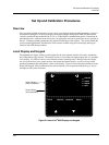
Pressing the SET UP key on the keypad provides access to the various set up groups and allows you to set
up operating parameters, (such as input types and alarms), calibrate the actuator’s inputs and outputs, set
communications, and check actuator status.
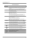
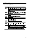
Table 8 on the next page lists the set up groups that are
available by using the SET UP and FUNCTION keys on the keypad.
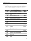
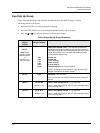
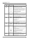
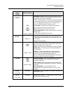
Table 8 Set Up Groups
Set Up Group Title Pressing the FUNCTION Key Allows You to… For Details, See
SET
INPUT
Select and set various parameters associated with the
input signal to the actuator.
Table 10
SET
RELAYn
n = 1, 2, 3, or 4
Select relay functions. NOTE: Set Relay groups will
show on display only if relays are installed in the
actuator.
Table 13
SET
CUROUT
Select the output signal type of the actuator.
Table 15
SET
COMM
Select communication parameters for remote control of
actuator when connected to a SCADA system.
Table 16
SET
DIGINP
Select the parameters for external digital input states.
Table 17
SET
DISPLA
Select and set parameters for the local display.
Table 18
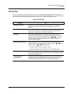
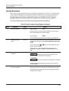
CAL
INPUT
Calibrate input zero and span values.
Calibration
Procedure,
Table 25
CAL
MOTOR
Calibrate zero and span values for motor operation.
ATTENTION
When calibrating the motor to a short stroke range,
you must reset the end-of-travel limit switches. See
Setting End-of-Travel Limit Switches.
Calibration
Procedure,
Table 26
CAL
CURENT
Calibrate actuator output. Calibration
Procedure,
Table 27
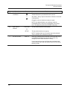
SET
LOCK
Set or change security password. Enable or disable
security access to set up parameters and calibration
set up.
Table 19
READ
STATUS
Display operating and alarm status. Display self-test
diagnostic results.
Table 20
SET
DRVINF
Display and/or set various parameters specific to the
actuator.
Table 21