


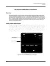
Set Up and Calibration Procedures
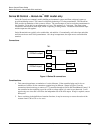
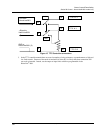
Local Display and Keypad
32 HercuLine™ 2000 Series Actuator - Installation, Operation and Maintenance Manual Revision 7
7/08
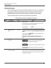
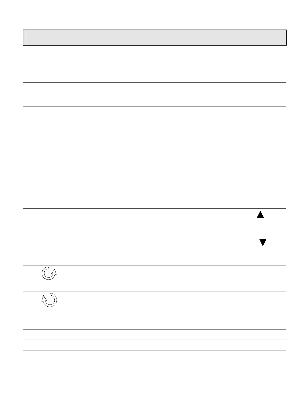
Table 6 Keypad Description
Key or
LED Indicator
Function
SET UP
Places the actuator in the set up group select mode. Sequentially displays the set
up groups and allows the FUNCTION key to display function parameters within the
set up group.
See Set Up and Calibration Procedures (page 31)Error! Reference source not
found. for descriptions of the various options available in the set up groups.
FUNCTION
Used in conjunction with the SET UP key to select the individual functions of a
selected configuration set up group.
Used during field calibration procedure.
MAN/AUTO Alternately selects:
MAN - Actuator is in Manual mode.
AUTO - Actuator is in Automatic mode.
NOTE: When in Manual mode the POS display is automatically selected so you
can use the up and down arrow keys to drive actuator motor manually.
NOTE: This button is disabled if MAENAB is set to DIS. See
Table 19 (page 53).
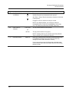
DISPLAY
Pressing this key repeatedly cycles through the operating parameters that can be
shown on the lower display.
INP – Input. Shows the value of the actuator input.
OP – Output. Shows the value of the actuator output
DE – Deviation. Shows deviation between input value and actuator position.
POS – Position. Shows current actuator position.
INCREMENT
Increases the configuration values shown on the display. Also shown as
.
In manual mode and POSition display selected, pressing this key will drive actuator
motor in direction of increasing signal input.
DECREMENT
Decreases the configuration values shown on the display. Also shown as
.
In manual mode and POSition display selected, pressing this key will drive actuator
motor in direction of decreasing signal input.
☼
Indicates the movement of the actuator arm in the counterclockwise direction.
NOTE: Actuator rotation is the direction of the output shaft when facing the end of
the shaft and refers to the direction of rotation on increasing signal.
☼
Indicates the movement of the actuator arm in the clockwise direction.
NOTE: Actuator rotation is the direction of the output shaft when facing the end of
the shaft and refers to the direction of rotation on increasing signal.
☼ STALLED
Indicates that the actuator has detected a motor stall condition.
☼ ALARM
Indicates a programmed alarm condition exists.
☼ MANUAL
Indicates actuator is in manual mode
☼ AUTO
Indicates actuator is in automatic mode.