


Set Up and Calibration Procedures
Setting End-of-Travel Limit Switches
78 HercuLine™ 2000 Series Actuator - Installation, Operation and Maintenance Manual Revision 7
7/08
Setting End-of-Travel Limit Switches
ATTENTION
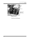
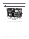
Referring to
Figure 31. The first two cams (starting from the front) are for the 0% and
100% limit switches (Switch #1 and Switch #2) and should not need any adjustments as
they are factory set to stop the drive at 0% and 100%. See Figure 30 for limit switch
settings.
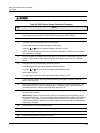
NC
NC
100%
0%
8 (SW1 COM)
9 (SW2 COM)
7
155
14
SW#1
SW#2
LEFT HAND
POINTER
SCALE
END OF TR
A
VEL LIMIT SWITCH S ETTINGS
(FACTORY SET AT 0% AND 100%)
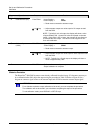
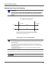
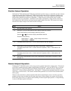
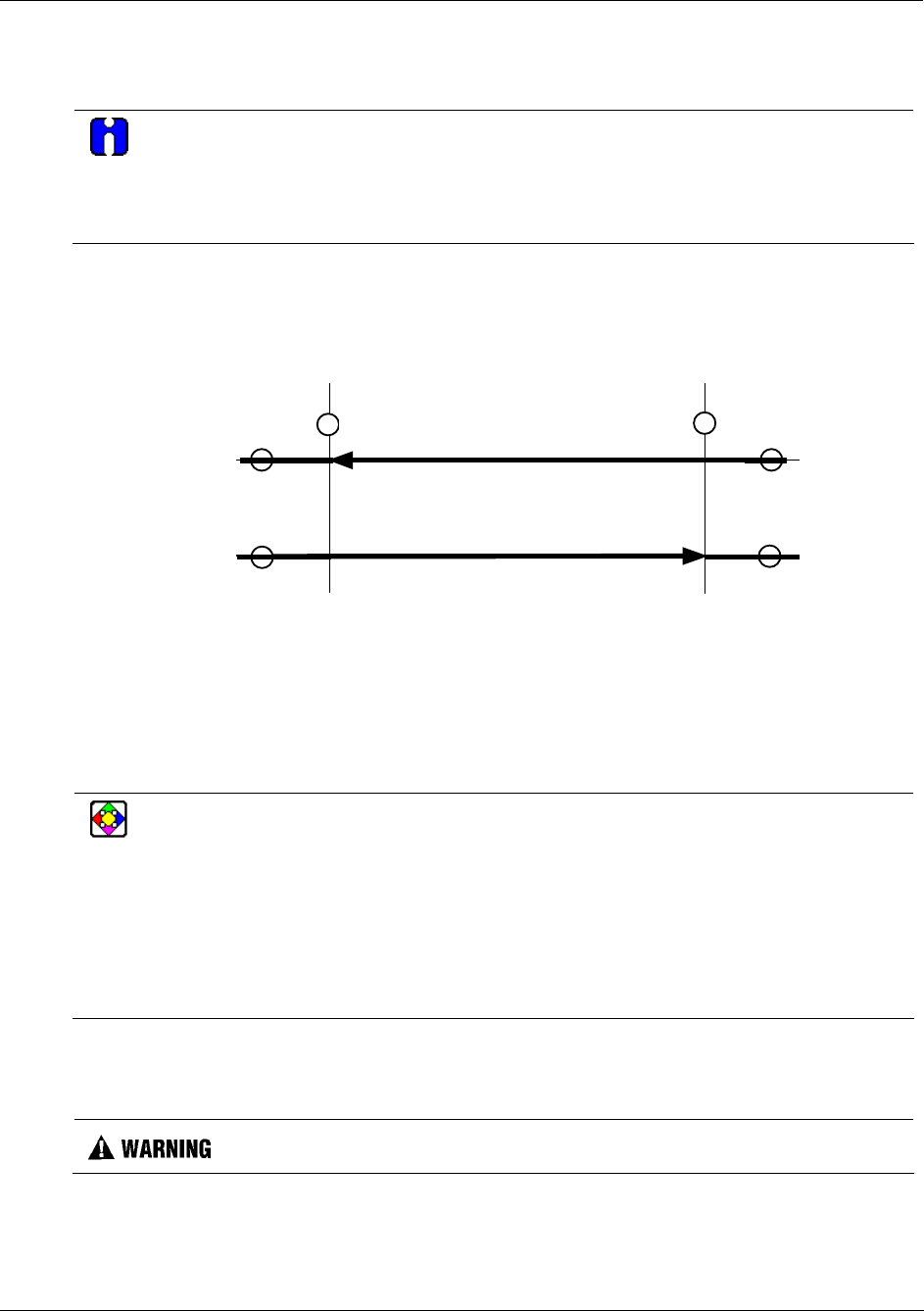
Clockwise and counterclockwise rotation is the direction of the output shaft
when facing the end of the shaft. As shown, clockwise rotation of the output
shaft activates SW 1 (at 0% on the left hand pointer scale) and CCW rotation
activates SW 2 (at 100% on the left hand pointer scale). Terminal numbers
are next to the circles.
Clockwise Rotation
Counterclockwise Rotation
Figure 30 End of Travel Limit Switch Settings
REFERENCE
An unactuated switch will have its normally closed (NC) contacts closed and its normally open
(NO) contacts open.
An actuated switch will have its NC contacts become open and its NO contacts become
closed. Both NC and NO contacts are available at the terminal block. See
Figure 8 (page 18)
and
Figure 9 (page 19).
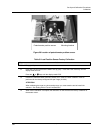
An unactuated switch has its roller arm in the up position when adjacent to the reduced
diameter portion of the cam.
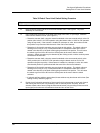
If it becomes necessary to do adjust the limit switch cams in the field, use the procedure given in
Table 32.
While the unit is powered, a potentially lethal shock hazard exists inside the case.
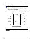
Clockwise and counterclockwise rotation is the direction of the output shaft when
facing the end of the shaft. As shown, full clockwise rotation of the output shaft
activates SW1 and CCW rotation activates SW2.