


Start-Up/Operation
Introduction
Revision 7 HercuLine™ 2000 Series Actuator - Installation, Operation and Maintenance Manual 83
7/08
Start-Up/Operation
Introduction
After the actuator is completely installed, wired, and the preliminary adjustments made, it is advisable to check
the operation of the actuator and controlled device before placing it in service. In other words, operate the
controlled device and check its direction of travel in response to an increase of the input signal and make sure it
is correct for the process. Actuators having the optional auto-manual switch must have the knob set in the
AUTO position.
This section provides a checklist that can be used to do a walk-through with the actuator before it is actually
used for control. Other features which may be helpful in understanding actuator operation are also provided.
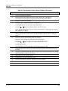
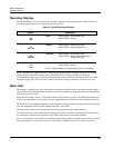
Power-up Diagnostics
When power is applied to the actuator, the actuator electronics performs a diagnostic routine on various device
components. These tests include a:
• RAM diagnostic (RAMTST),
• Check of the electrically eraseable PROM (SEETST),
• Verification that valid parameter values are in the actuator configuration (CFGTST),
• Verification of valid calibration values (CALTST)
• Test of the local display and LED indicators (all display segments and LED indicators light simultaneously).
The local display shows the status of the diagnostics as they are completed during power up. TEST DONE is
shown on the display when diagnostics are complete and actuator should be in AUTO mode. See
Table 20 for
more information on the power up diagnostics.
Operations Checklist
To make sure that the actuator is properly installed and set up for your particular application, you should check
and verify the following:
• Verify that the configuration is correct for your application by stepping through all set up groups and
checking the setting of all set up parameters.
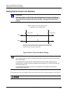
• Verify operation of end-of-travel limit switches.
• Verify operation of auxiliary switches or relay function (if installed).
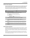
• Check operation of AUTO - MANUAL DRIVE switch (if present), by setting the knob to the CW and CCW
- MANUAL positions. The output shaft should rotate in the direction indicated by the knob. The LED
indicator on the local display should also indicate the actuator is in manual mode.