


JKSSS+ Series - 91
JKSSS+ Series 2.3 - 4.2KV
-
• Phillips screwdriver
• 3/8” 12 point socket set
• 2 9/16” wrenches
• ½” wrench
• AC/DC Multimeter
• JKSSS+ manual (refer to drawings in this section)
1. Verify that no DC or AC voltage is present on any of the power compo-
nents.
2. Disconnect all four wires connected to TB1 positions 1-3 on the tempera-
ture CT board.
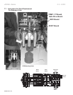
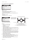
3. Disconnect the 4 red transformer wires on each of the gate drive boards.
These would be TB1, positions 3 and 5 for each gate drive board. Typically,
the 2300V unit will have only 4 wires per phase to disconnect, a 4160V unit
will have 8 wires per phase, and a 6000 - 7200V unit will have 12 wires per
phase. (Note: the 7200V/600A unit will also have 24 wires.)
4. Use the 9/16 wrench and carefully unbolt all of the line and load power con-
nections attached to the heat sinks. Note: If the unit is a 6000 - 7200V, re-
move the power strap connecting one side of the stack to the stack directly
below it.
5. Before removing the ber optic wiring, make a note of the label on the
ber cable to ensure they are placed exactly in the same socket they were
removed from. Now remove all ber optic connectors on the stack. Gently
push on the connector tab and pull with a gentle left-to-right motion on the
connector in the direction away from the ber optic device. Two connectors
will be found per gate drive board and one duplex connector will be found
on the small Temp/CT board on top. Caution: Do not touch the tip of the
connectors or contaminate the connection sockets with any dust or foreign
material.
6. Remove the wires from the Temp/CT board terminal block (3 screws).
7. Use a 9/16” socket with a 6” extension to remove the lower bolt that
routes through the front face of the heat sink and into the isolation standoff
mounted to the white panel. Then carefully hold the heat sink in place with
one hand and remove the top bolt from the heat sink.
8. Ensure the ber optic connectors and all wires are positioned out of the
way, and then the heat sink can be gently removed from the unit.
DANGER
HAZARDOUS VOLTAGE
Disconnect all power supplying this equipment prior
to working on it.
Failure to follow this instruction will result in death
or serious injury.