


JKSSS+ Series - 17
JKSSS+ Series 2.3 - 4.2KV
Ensure that safety signs are not covered or obscured by paint.
The setting of any adjustable current and voltage trip mechanisms should be veried to
the proper values.
Damage from faults can be reduced if devices used for short circuit and ground
fault protection are chosen and set to operate at values as close to minimum as feasible,
while allowing normal transients.
All switches, relays and other operating mechanisms should be manually exercised to
make certain that they are properly aligned and operate freely.
Operating mechanisms such as interlocks, key switches, etc. should be checked for func-
tion as intended for protection of personnel and equipment.
Overload relay settings should be checked to be sure they are selected and adjusted to
the proper settings per the load nameplate data.
Power circuit fuses were selected and installed in accordance with the application re-
quirements. Fuses must be completely inserted in their holders. Instruction on removing
and installing the fuses can be found in one of the following manuals: VF010H03 (Fixed
Type) or VF010H01 (Drawout Type).
With incoming power isolated and all loads disconnected electrically, the control cir-
cuit and other mechanisms should be exercised to determine that the devices operate
properly. An auxiliary source of control power will be necessary to provide power to the
electrical operators.
The ground fault protection system (if furnished) should be tested in accordance with the
instructions furnished with the device.
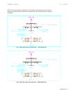
An electrical insulation test should be performed to ensure that the controller and asso-
ciated eld wiring are free from short circuits and grounds. The preferred method is to
perform a dielectric test at 2.25 times the nominal system voltage plus 2000 volts. This
should be done phase-to-ground, phase-to-phase and phase-to-neutral (if applicable),
with all switches and circuit breakers opened. Disconnect any devices which may have
limited dielectric strength and that are not intended for this test.
The light or buzzer, or both, used to indicate breakdown should be calibrated to indicate
failure with an output current between 1.5 and 2.0 milliamperes per 1000 volts applied.
All devices must be set to their normal or OFF position before energizing incoming power.
WARNING
WARNING
WARNING