


JKSSS+ Series - 11
JKSSS+ Series 2.3 - 4.2KV
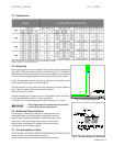
1.9Electronics
The JKSSS+ Series electronics systems are divided into two categories, Low Voltage
and Medium Voltage, based solely on where they are located in the starter structure.
electronics include the Keypad Operator Interface, CPU and Main
Power PC boards are located in an isolated Low Voltage Compartment of the
enclosure.
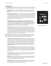
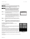
· a 2 line x 20 character LCD display with backlight-
ing for low ambient conditions. The display reads out in truncated English and
can show multiple data points in each screen. Also included are 12 LED indica-
tors, which include Power, Run, Alarm, Trip and the status of the 8 Aux. Relays.
It communicates to the CPU via a serial link and, if necessary, can be remotely
mounted up to 1000’ from the soft starter.
· where the microprocessor and communications coprocessor
reside. It is attached to the main power board, and communicates to it and
the Keypad Operator Interface via serial links. The CPU determines operating
functions, stores user programming and acts upon feedback signals for faults,
metering and historical data. This board also contains the ash EPROM and
SRAM memory, as well as the Analog I/O and terminations.
· is also referred to as the Firing Board. It contains the
Digital I/O relays and interfaces to the TCB board (see below) for user inter-
face. It also controls the sequencing of the Isolation and Bypass contactors with
the SCR ring. This board generates all ring signals for the SCR stacks and
receives feedback signals from ber optic transmitters. It converts analog levels
to digital signals for the CPU. These ring pulses are via ber optic signals to
isolate them from the Medium Voltage environment.
are located in the medium voltage and low voltage sections of
the soft starter. The main line power must be disconnected before these electronics
can be accessed. They include the TCB, Gate Drive and Temp/CT boards.
· is the user connection interface board. It
is located in the Low Voltage section in order to satisfy UL termination require-
ments, and does not connect directly to the medium voltage components other
than the contactor coils. This board contains the user terminal blocks, output
relays (duplicated), inputs and control power connections. It also contains ad-
ditional timed relays for interfacing with Power Factor Correction contactors (if
used) and other external devices. Please note Power Factor Capacitor warn-
ings in Section 2.8.
· located directly on the SCR stacks. These boards com-
municate to the Main Power board via ber optic cables. They amplify the gate
pulse signals with power from the Ring Transformers to create the Sustained
Pulse Firing of the SCRs. There is one Gate Drive board for each pair of SCRs
in each stack.
· are attached to the Gate Drive boards on the SCR stacks
and provide the heat sink temperature and current signals back to the Main
Power Board via ber optic cables.
· are attached to standoffs mounted on the SCR heat sinks and
are mounted directly below the Gate Drive boards. The MOV boards are used
to protect the gate/cathode section of the SCRs.
· are also attached to standoffs mounted on the SCR heat sinks
and are mounted below the MOV boards. The DV/DT boards are used to re-
duce voltage transients across the stack assemblies.
KeypadOperatorInterface