


JKSSS+ Series - 22
JKSSS+ Series 2.3 - 4.2KV
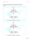
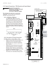
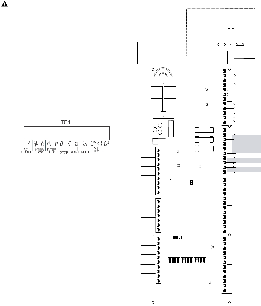
2.10ControlConnections-TCB(TerminalandControlBoard)
This will cause severe equipment
damage and possible fatal injury.
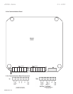
2.10.1JKSSSPlus-TCBBoard
The JKSSSPlus-TCB board provides
interconnections between the main power and
CPU boards and the customer’s control logic
connections. It is a 120Vac control board with
several auxiliary dry control contacts, built-in
time delay circuits and emergency bypass func-
tions. It also controls the sequence of the inline
isolation and bypass contactor and provides
provisions for shutdown interlocks. (seesection
2.10.2)
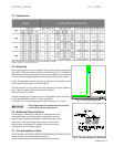
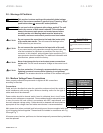
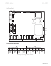
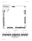
2.10.2DescriptionofTerminalConnections
• Positions 1 and 9 are the 120 Vac control power.
• Positions 2-3 and 4-5 are factory jumpers
installed and can be removed for customer’s
normally closed, dry, shutdown contacts (See
Fig. 2-1 above).
• Positions 6-7-8 are for either two wire or three-
wire start/stop logic. Two wire is connected to
positions 6 and 8 with a N.O. dry, maintained
start/stop contact. Three wire control connects
to 6 with 7 as the stop push-button, and the start
push-button is connected to 7 and 8.
• Positions 10-11-12 is a dry FORM C contact.
The contact is an immediate start/stop contact.
C
4
6
A1
A2
Main
C oil
10
9
A2
A1
B ypas s
C oil
8
7
PFC
TB4
TIME D
OUT
S TART
AUX
DELAY
Green
LED
NO
Time Delay
1
C
2
4
3
CNC
5
6
NO CNC
BOAR D
B ypas s Aux C onta ct
4
5
E xternal Overload
F us e Blown/
Disconnect
Interlock Input
3
2
1
57 6 14 3 2
TB8
AUX-S
PFC-S
PFC-C
AUX-C
DLY-C
DLY-S
TB7
6
7
At Speed
4
5
B ypass S ta tus
DUAL ADJ
CPU (AUX1) Fault
R un
1
3
2
10
ON
TB6
Dual Ramp
9
8
7
F us e Blown/
Disconnect Open
6
5
OFF
SW1
JP1
Remove JP1 for electronic
motor overload protection
during emergency
bypass operation
+12V
Lock Out
NO
OUT
TIME D
PFC
5 3467
7 6
2 1
2 15 4 3
LED
Green
P.F.C. CA P
7
8
9
NCNO
12
10
11
C NCNO
2
1
C NO
3
4
CNC
TB3
TCB
S TART
10
7
5
6
CNC
8
9
C
Fault
NCNO
11
12
NO NC
2
1
NO
C
120VAC
Delayed Start
Neutra l
3
2
HEATS INK
Line
1
-12V
LED
Green
LED
Green
HE ATSINK
T1
E2
E1
E4
E3
Inter
F2
LED
Green
TB2
F3
F1
8
4
5
3
NO
NC
6
7
S CN
9
10
NCNO
2
1
Source
AC
Lock
TB1
FAULT
FUSE
LED
Red
LED
Red
8
5
4
3
Lock
Inter
6
7
S tar t
S top
NO
9
10
Neut
AC
C
12
11
NC
Maintained
Momentary or Maintained
S ta rt / S top S witc hing
Momentary
S TOPS TART
120VAC
Source
120VAC
Neutral
Emergency Bypass
AUX Contacts
Emergency Bypass
Full Voltage S tart
Optional
Interlocks
{
{
{
FACTORY WIRED
DO NOT USE
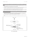
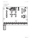
F1: Control Fuses for TB1 1 - 9
Part #ACG1A250 VAC or equivalent
F2: Contactor and relay output fuses
Part #ACG4A250 VAC or equivalent
F3: TB2 Pin #6
Part #ACG4A250 VAC or equivalent
Fuses
Customer Provided
Aux S tart
Output
WARNING