JKSSS+ Series - 4
JKSSS+ Series 2.3 - 4.2KV
1.3 Design Features
The standard JKSSS+ configuration is a complete NEMA Class E-2 motor
controller which includes the following features:
• Isolation Switch:
An isolation switch is provided in the incoming power section of the starter
assembly. The maximum voltage is 7200V.
Power is switched on and off to the controller by a fixed-mounted, externally-
operated, three-pole isolation switch. When the switch is in the opened
position,
incoming power is isolated from the controller compartment interior by
an automatic shutter. For additional safety, the load terminals of the switch are
automatically grounded when the switch is opened. This allows any stored
energy in the controller load circuit to be discharged by closing the contactor
using test power.
A viewing window in the Main Incoming Power Compartment allows visual
inspection of the disconnect blade status with the medium voltage door closed.
The external operating handle for the isolation switch is designed to accept up
to three external padlocks in the OFF position.
For additional information on the isolation switch, see instruction manual
VF010H01, VF010H02 or VF010H03.
• Power Fuses: As a NEMA Class E2 controller, current limiting primary power
fuses are provided for each incoming phase.
Typically the fuses are ANSI class “R” for units rated up to 4800V. The fuses
are sized according to motor locked rotor current and are coordinated with the
solid state overload relay. The fuse and overload coordination is designed to
allow the controller and contactor to clear low and medium level faults. This
prevents exceeding the contactor interrupt ratings. Fuses interrupt high level
faults that exceed the contactor interrupt ratings. Fuse holders include blown
fuse indicators (wired to the isolation contactor circuit) to disconnect all three
phases if any one of the fuses clears (see section 2.7).
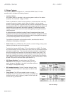
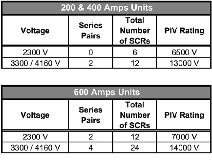
• SCR Power Modules: For each phase, the SCRs are
matched devices arranged in inverse parallel pairs and in
series strings as indicated in the chart to facilitate sufficient
PIV ratings for the applied voltage.
• RC Snubber Networks: Provide Transient Voltage Protec-
tion for SCR Power Modules in each phase to reduce dv/dt
damage.
• Firing Circuit: The SCRs are gated (turned on) using a
Sustained Pulse Firing Circuit. This circuitry is amplified and
isolated from the control voltage by means of fiber optics for
current and ring transformers.
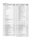
Unit PIV Ratings


