


JKSSS+ Series - 5
JKSSS+ Series 2.3 - 4.2KV
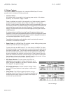
Vacuum contactors are provided for both In-Line Isolation and SCR
Bypass. The contactor voltage ratings are: 7.2kV for 2300 - 6900V units.
A sequencing feature controls the contactors. Under normal operating conditions
this ensures that both contactors make and break under no-load conditions to
maximize contactor life. Vacuum contactors are rated for the maximum starting
requirement of the unit design. The Bypass Contactor is rated to be capable
of emergency start. For further information on the vacuum contactor, see the
instruction manual on the vacuum contactor supplied with the equipment, and
also either VF010H01 (400A Drawout Type) or VF010H03 (Fixed Type).
The JKSSS+ Series is also offered in an optional “Soft
Start Only” package for use in retrotting behind an existing customer supplied
line start controller. In this conguration,
JKSSS+ unit, so
proper interlocking of sections containing medium voltage becomes the install-
er’s responsibility.
All retrot “Soft Start Only” packages must be used with complete line isola-
tion using a contactor or other “air-gap” device. The Optional “Soft Start Only”
includes overload protection in normal operation mode and will sequence the
isolation contactor, so all logic control should be done at the JKSSS+ control
unit. Avoid turning the JKSSS+ on and off using the isolation device.
1.4StructureandPowerBus
The JKSSS+ Series is a heavy duty design. Special consideration has been given
to the enclosure and unit design to ensure that it is suitable for most applications and
environments.
: 11 gauge frame with 16 gauge side, back and top sheets. Doors are
12 gauge steel. The enclosure assembly is NEMA / EEMAC type 1 as standard.
Type 12 and 3R are available as an option.
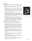
In a typical arrangement, each enclosure is divided vertically into
three major compartments, each with a separate door. In the JK400, the upper-
most and lowermost compartments contain medium voltage controller compo-
nents (>600V) while the middle compartment contains low voltage components
(<600V). Other variations of this basic arrangement are possible.
The houses the main disconnect switch,
amain power fuses and input isolation contactor. A viewing window provides
clear indication of the switch position without opening the compartment.
Bus Compartment contains the horizontal bus bars (if provided). Top, bottom or
side cable entry can be made with minimum bending.
One or more contain the bypass vacuum con-
tactors, SCR power modules, instrument transformers and all other medium
voltage devices. Adequate room is provided for motor lead connections to be
made with minimum conductor bend.
A houses the digital microprocessor
controller and LCD keypad operator interface, along with any other low voltage
devices. This allows the operator to make adjustments without exposure to the
line voltages.