


JKSSS+ Series - 49
JKSSS+ Series 2.3 - 4.2KV
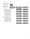
the Voltage Ramp or the Current Ramp. Every
load requires some amount of torque to start from
a standstill. It is inefcient to begin ramping the
motor from zero every time, since between zero
and the WK2 break-away torque level, no work is
being performed. The initial torque level should be
set to provide enough torque to start rotating the
motor shaft, enabling a soft start and preventing
torque shock damage. Setting this start point too
high will not damage the starter, but may reduce
or eliminate the soft start effect.
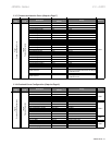
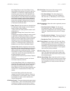
: Sets the maximum allowable time
for ramping the initial voltage or current (torque)
setting to either of the following:
1) the Current Limit setting when the motor is still
accelerating, or
2) full output voltage if the Current Limit is set to
maximum.
Increasing the ramp time softens the start process
by gradually increasing the voltage or current.
Ideally, the ramp time should be set for the longest
amount of time the application will allow (without
stalling the motor). Some applications require
a short ramp time due to the mechanics of the
system (i.e. centrifugal pumps, because pump
problems can occur due to insufcient torque).
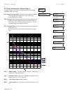
Sets the maximum motor current
the starter will allow during Ramping. As the motor
begins to ramp, the Current Limit feature sets a
ceiling at which the current draw is held. Current
Limit remains in effect until the following occurs:
1) the motor reaches full speed (detected by the
At-Speed detection circuit) or
2) the Overload Protection trips on Motor Thermal
Overload.
Once the motor reaches full speed, the Current
Limit feature becomes inactive.
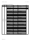
In the Voltage Ramp Prole, the voltage output is
increased until it reaches the Current Limit. Ramp
time is the maximum amount of time it takes for
the voltage to increase until the Current Limit
setting takes over. With some load conditions, the
Current Limit is reached before the Ramp Time
expires.
The Current Ramp prole varies the output
voltage to provide a linear increase in current up
to the Maximum Current setpoint value. A closed
loop feedback of motor current maintains the
Current Ramp prole.
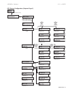
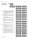
The same options and screen setups
as Start Ramp 1. Note: CUSTOM ACCEL CURVE
overrides the voltage or current start in Ramps 1
and 2 when selected to be the start control mode.
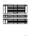
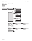
: Used as an initial energy burst in
applications with high friction loads.
: The initial voltage (as a
percent of full voltage value) that is needed to
start the motor (i.e. Breakaway or Initial Torque).
• : The time the initial torque boost
is applied.
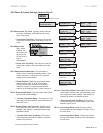
: Allows the motor to gradually come to
a soft stop.
: The rst part of
the deceleration ramp. The soft starter initially
drops to this voltage level upon receiving a STOP
command. (Represented as a percent of voltage
value.)
: The drop-off point of
the deceleration ramp. (Percent of voltage value.)
: Decel ramp time.
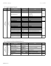
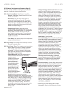
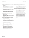
: Used with an AUX 5-8 relay. When
enabled, and upon a start command, it waits until
the programmed time plus the run delayed time
has expired. The relay energizes and remains so
until a stop command is received. It de-energizes
upon receiving a stop command.
: Can be used with an AUX 5-8
relay. The delay timer begins upon receipt of the
start command. The relay will then drop out when
the time has expired.
: Used with an AUX 4 relay, it
waits until after the motor reaches the end of ramp
and the programmed delay time has expired. The
relay energizes until a stop command has been
received.