


JKSSS+ Series - 95
JKSSS+ Series 2.3 - 4.2KV
9. Verify or wire a 120Vac plug to the TEST plug supplied by the factory.
10. Remove all both power fuses on the medium voltage CPT (single
phase control power transformer), if present..
11. Remove 3 fuses from the medium voltage potential transformer (PT).
12. Verify the 120-volt test switch is in the “NORMAL” position.
13. Connect test power to test plug connector and place the 120-volt test
switch to the “TEST” position.
14. The keypad should be energized with the “Power LED,” Stop LED.
15. Close the temporary Start switch, which is connected to the control
board.
16. The Main Vacuum contactor should close and the keypad should
trip on “Under Voltage” Open temporary TEST switch and reset CPU
fault.
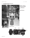
17. Connect the Secondary of the TEST PT to Panel TB1 positions 1 -
phase A, position 3- phase B, and position 5 - phase C on the main
ring board (JKSSS+-MB). It is physically located behind the low
voltage compartment door. (Screw terminal block)
18. Verify all connections are good and then energize the low voltage of
either 480 or 240 volt, three phases.
19. Use the multimeter on the AC scale and verify 3 phase 120Vac
(phase to phase) at TB1 pins 1, 3 and 5 of the main ring board.
20. If all 120Vac 3 phase is present then de-energize low voltage of 480
or 240Vac.
21. Re-energize the low voltage of 480 or 240Vac.
22. Now all test voltages should be present 480 or 240Vac and three
phase 120Vac (TEST PT) and 120Vac single phase for control
power.
23. Close the temporary Start switch and the test motor should spin up
smoothly.
24. Use the Multimeter on the AC scale and check (phase to phase)
voltages on T1, T2 and T3 motor leads. The voltages should be bal-
anced.
25. If the motor doesn’t spin up smoothly the soft starter is malfunction-
ing. Proceed to step 27 for troubleshooting.
26. If the motor starts and runs smoothly then repeat this procedure in
reverse to remove all test connect and reinstall all fuses.
Tools: Ungrounded Oscilloscope
27. Open test switch and stop motor.
28. Change Setpoint Page 5 AUX4 is set at non-fail safe. Change it to fail
safe.
29. Observe bypass contactor closes immediately.
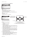
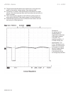
30. Place the Oscilloscope on the 2msec time scale and 1 Volt per
division.
31. Connect the Oscilloscope probe to the Gate and Cathode of the
SCRs.