


JKSSS+ Series - 82
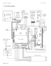
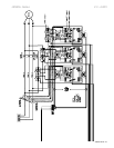
JKSSS+ Series 2.3 - 4.2KV
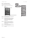
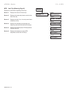
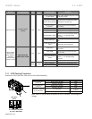
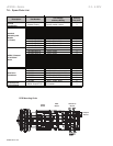
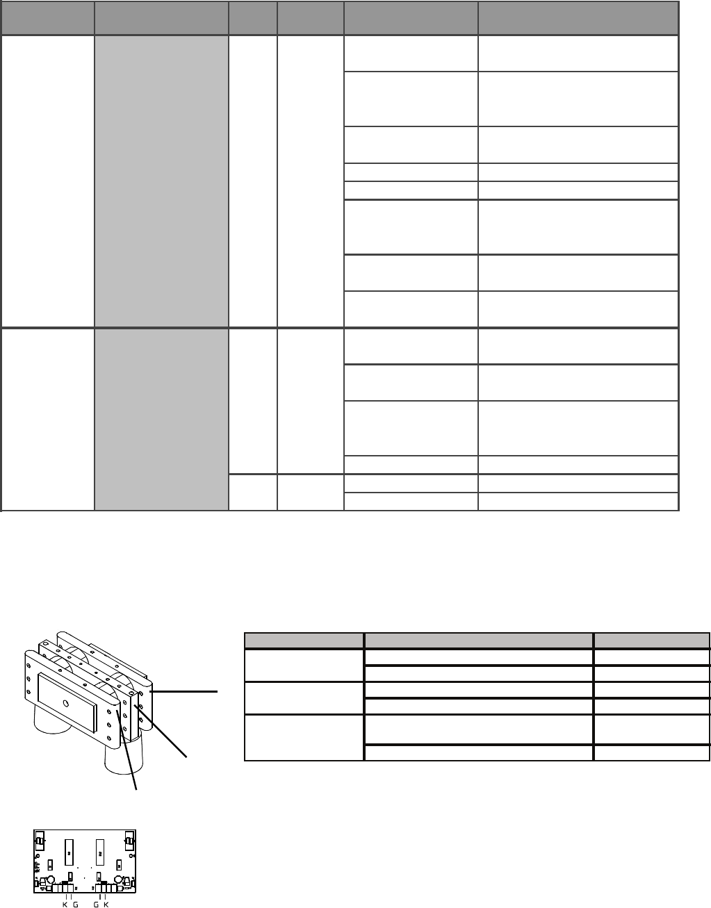
Perform the SCR Heat Sink Ohm test on each Stack Assembly.
A
B
C
Note: Allow 15 minutes after shutdown for DV/DT network to discharge DC
voltage.
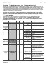
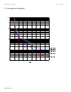
Board
Problem CPU LCD Display LED
Aux
Relay
Possible Cause Solutions
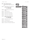
No control voltage applied
to control board
Apply control voltage to TB1 pins 1 and 6
on the power board
Control power transformer
failure or CPT fuse failure
Remove power and replace the power
transformer or the CPT fuse
Start circuit wired
incorrectly
Remove power and correct the start
circuit wiring
No start command Apply the start command
No 3 phase line voltage Apply 3 phase line voltage to the unit
Shorted SCR in starter
Remove power and test SCR(s). Refer to
Section 7.1.1 for the SCR testing
procedure
Faulty control logic
Remove power and repair the control
logic.
Failure of main circuit
board
Replace the main circuit board
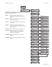
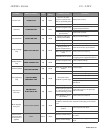
Faulty motor
Check the motor and the motor
connections
Faulty SCRs
Remove power and perform the SCR
device checks
Faulty gate/cathode on
SCRs
Remove power and test SCR(s). Refer to
Section 7.1.1 for the SCR testing
procedure
Faulty main circuit board Replace the main circuit board
Faulty motor/wiring
Troubleshoot and repair/replace wiring
Faulty main circuit board
Replace the main circuit board
Motor will not start
Any fault indication
message
Trip
AUX1
Trip
AUX1
Alarm
AUX2
Motor vibrates/
Motor growls
while starting or
extremely
unbalanced motor
currents run mode
IMBALANCE TRIP
IMBALANCE ALARM
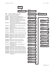
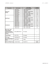
Test To PerformOhm Meter ReadingTest Result
Greater than 10K Ohm
Pass
Less than 10K Ohm
Fail
Greater than 10K Ohm
Pass
Less than 10K Ohm
Fail
8 to 100 Ohms
Pass (Typical 8 to 20
Ohms)
Less than 10 or greater than 100 Ohms Fail
From Position A to
Position B
From Position B to
Position C
Gate (G) to Cathode
(K) for each SCR