JKSSS+ Series - 9
JKSSS+ Series 2.3 - 4.2KV
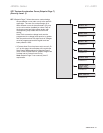
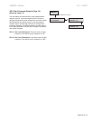
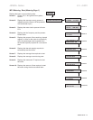
· Power is immediately removed from the motor and the
soft starter returns to the Ready Mode.
Additional protection features activated when the stop command is given include:
· Coast-Down / Back Spin Timer
· Starts-per-Hour
· Time Between Starts
· External Input Faults
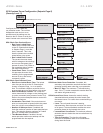
1.7ThermalOverloadProtection
The JKSSS+ Series plays an important role in the protection of your motor in that it
monitors the motor for excessive thermal conditions due to starting, running or even
ambient conditions. The soft starter has a Dynamic Thermal Register system in the
CPU that provides a mathematical representation of the thermal state of the motor.
This thermal state information is kept in memory and is monitored for excesses in
both value and rate of change. Input is derived from current imbalances and RTD
measurements making it dynamic to all processes involving the motor. The starter
monitors these conditions separately during Start and Run modes to provide proper
thermal overload protection at all times.
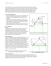
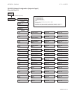
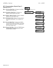
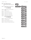
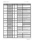
is selectable using one of three methods:
· I
2
t data is accumulated and plotted based on an Overload
Curve selected in programming. This is programmed per NEMA Class 5-30
standard curves and is based on the Locked Rotor Current (from the motor
nameplate) as programmed into the soft starter.
· The user enters a measured amount of thermal
capacity from a pre-selected successful start as a setpoint to the Thermal Reg-
ister for the soft starter to follow.
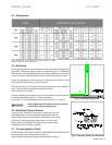
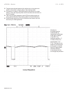
· The user sets the soft starter to the “LEARN”
mode and starts the motor under normal starting conditions. The CPU then
samples and records 100 data points during the start curve, analyzes them and
creates a graphical representation in memory. The soft starter is then switched
to Curve Follow protection mode and monitors motor performance against this
curve. This feature is especially useful in initial commissioning tests to record a
base line performance sample (in this case, it is not necessarily used for motor
protection).
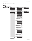
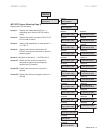
is initiated when the starter determines that the
motor is At-Speed. Overload Protection is initiated when the motor RMS current
rises above a “pick-up point” (as determined by the motor nameplate FLA and
service factor). Run mode protection is provided by the CPU monitoring the Dy-
namic Thermal Register. Data for the Dynamic Thermal Register is accumulated
from I
2
t calculations and cooling rates. A trip occurs when the register reaches
100% as determined by the selected Overload Protection Curve (NEMA Class
5-30 standard curves) and is based on the programmed Locked Rotor Current
indicated on the motor nameplate. The Dynamic Thermal Register is altered, or
“biased”, by the following conditions:
· Will bias the register higher to add protection from ad-
ditional motor heating during a current imbalance condition.
· Provided when the motor current drops below the pick-up
point or the motor is off line. The cooling rate is lower for motors that are off-line
(such as after a trip) since cooling fans are also inoperative.