


JKSSS+ Series - 94
JKSSS+ Series 2.3 - 4.2KV
• Phillips screwdriver
• Medium voltage fuse pullers if available
• Two control power transformer (Test PT) 500 VA minimum
• 120Vac control power (Test plug)
• Low voltage motor strapped for the proper voltage (typically 5 HP or
less)
• Oscilloscope if available
• Wire jumper
• Test switch (single pole i.e. - light switch)
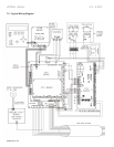
• Manual (reference drawing above)
Procedure:
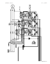
1. Verify that no DC or AC voltage
is present on any of the power
components.
2. Verify setup of control power
transformers for the proper
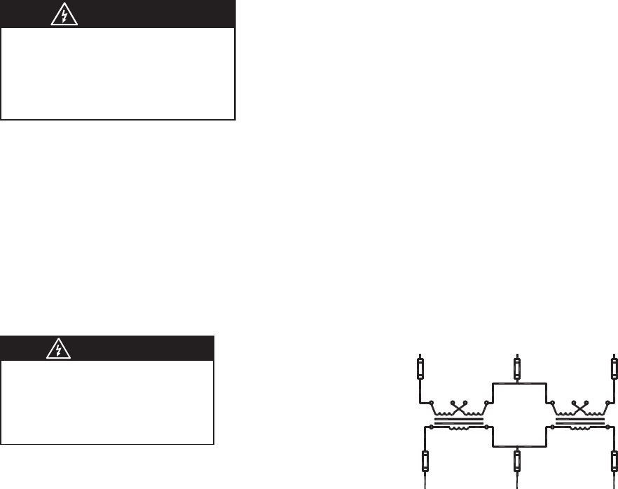
voltage. If using 480Vac or 240Vac 3 phase verify transformers are
strapped for that voltage. See above drawing. Congure as an open
delta for 3 phase as shown in drawing.
3. Verify medium voltage disconnect is open and pull medium voltage
fuses including PT and CPT fuses.
4. Connect 3 phase power 480 or 240Vac to the down stream side of
the fuses. Do not connect to disconnect side of fuses. Depending on
the small test motor used will depend on what size cable or current
that is required. Also, connect the Primaries of the TEST PT in the
proper phase sequence of A-B-C.
5. Disconnect medium voltage motor.
6. Connect low voltage motor. (Typically 5 HP or less)
7. Connect a wire jumper between TB8 pins 1 and 2 on the TCB (con-
trol board) to bypass fuse blown and open disconnect fault. The
TCB is located in the low voltage compartment.
8. Install a switch on TB1 pins 1 and 8 on the TCB (control board) to
bypass all interlocks (TEST Switch).
DANGER
HAZARDOUS VOLTAGE
Disconnect all power supplying this equipment prior
to working on it.
Failure to follow this instruction will result in death
or serious injury.
DANGER
HAZARDOUS VOLTAGE
Remove all medium voltage fuses to prevent back-
feeding transformers.
Failure to follow this instruction will result in death
or serious injury.
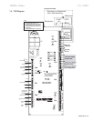
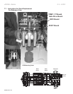
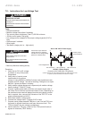
Construct an open delta low
voltage source for powering
the MVC for low voltage testing
(Minimum of 500VA each)
Connect to MVC3-MB (Main Firing Board)
Caution: Remove the three phase transformer PT fuses and CPT fuses
on panel to prevent backfeed to the Medium Voltage
Ensure proper
phase sequence
PTs
TB1 Terminal 1
Low Voltage Panel
TB1 Terminal 3
TB1 Terminal 5
120 VAC 3 Phase Output
H2
H2
X2X2
X1
X1
H1
H1
BC
A
BC
A
480 or 240 VAC 3 Phase Supply