JKSSS+ Series - 57
JKSSS+ Series 2.3 - 4.2KV
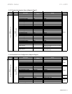
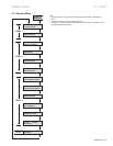
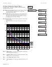
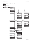
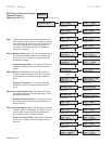
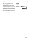
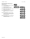
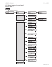
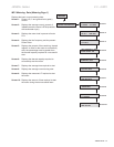
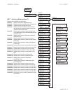
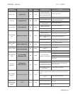
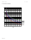
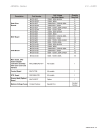
SP.6UserI/OConguration(SetpointPage6)
(SecurityLevel:2)
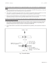
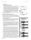
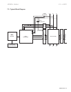
The controller can be congured to accept a tachometer
feedback signal through the 4-20mA input.
SP6.1 The rst screen of setpoint page 6 is TACHOMETER
SCALE SELECTION. When this is set to
ENABLED, the user will need to input the
tachometer scale of the 4-20mA input range.
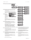
: The unit is looking
for an RPM value to assign to the lowest point on
the scale. This value should represent the motor
at zero speed.
: The unit is looking
for an RPM value to assign to the highest point on
the scale. This value should represent the motor
at full speed.
When enabled, the
underspeed or overspeed must be selected for the
Tach Accel Trip. If underspeed is selected, only
the Tach Underspeed Trip Point will be used. If
overspeed is selected only the Tach Overspeed
Trip Point will be used.
This is the duration of time
before the tachometer begins to sample.
The minimum value of
motor RPM which must be achieved before the
Tach Ramp Time sample is taken.
The maximum motor RPM
allowed when the Tach Ramp Time sample is
taken.
: The duration of time that
the Tach Accel trip condition must persist before a
trip is generated.
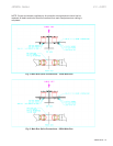
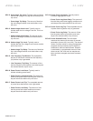
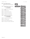
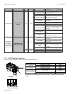
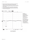
SP6.3 The controller provides two 4-20mA analog outputs.
Each analog output is independent of the
other and can be assigned to monitor different
functions. The available output ranges are RPM,
Hottest Non-Stator (Bearing) RTD, Hottest Stator
RTD, RMS current, % Motor Load, or kW.
– Select a function from
the available options to be transmitted from
the 4-20mA output. Note: If selecting RPM,
the Tachometer feedback input signal must be
present in order for the controller to give proper
output. If selecting RTD, the RTD option must
be installed and an RTD input signal must be
present for a proper output to be given from the
analog output.
: Enter a value that the
4mA level will represent for the selected function;
typically this value should be 0.
Enter a value that
the 20mA level will represent for the selected
function.
– All of the setpoints and setup
screens for Analog Output #2 are the same as
those for Analog Output #1.