


JKSSS+ Series - 51
JKSSS+ Series 2.3 - 4.2KV
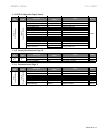
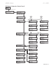
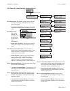
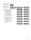
SP.3Phase&GroundSettings(SetpointPage3)
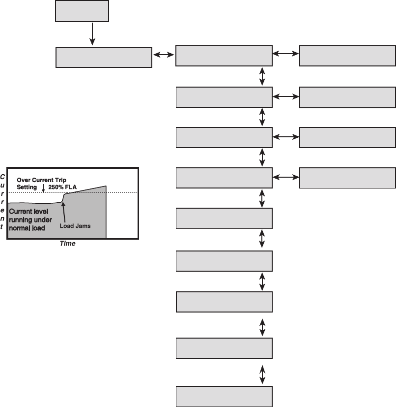
: Typically used to indicate
the motor is severely overloaded and at which
point a trip occurs.
The amount of time the
overcurrent condition must exist before a trip will
occur.
SP3.6 Phase Loss
: When
enabled, the
soft starter will
trip the motor
off-line upon a
loss of
phase power.
The amount of time the
phase loss condition must exist before a trip will
occur.
The soft starter is
continuously monitoring the phase rotation. Upon
a start command, a trip will occur if it detects a
change in the phase rotation.
There are two possible phase
rotation options: ABC or ACB. This setpoint
monitors the wiring to ensure that the phase
rotation is correct. To view the present phase
rotation, go to Metering Page1, screen number 4.
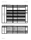
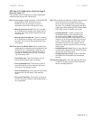
Typically used to warn of low
level ground current leakage.
The amount of time
that the ground fault condition must exist before an
alarm will occur.
Typically used
to trip the motor on a low level of ground current
leakage. This setpoint is intended to detect high
impedance faults.
The amount
of time that the ground fault condition must exist
before a trip will occur.
*Ground Fault Option must be installed
Used to trip the
motor (within milliseconds) upon detecting a high
level of ground current leakage. This setpoint is
intended to detect low impedance faults.
The amount
of time that the ground fault condition must exist
before a trip will occur.
Typically used to
indicate when the line voltage is too high. This is
an alarm level.
The amount of time
that the overvoltage condition must exist before a
trip will occur.
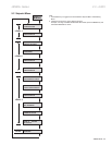
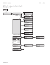
MENU
PAGE 3 PHASE &
GROUND SETTINGS
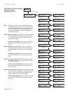
POWER FACTOR LEAD
P/F ALARM: OFF
Range: .01 - 1.00, OFF
Increments of .01
(Hit DOWN ARROW two times)
P/F LEAD ALARM
DELAY: 1 SEC.
Range: 1 - 120 SEC
Increments of 1
POWER FACTOR LEAD
P/F TRIP: OFF
POWER DEMAND
PERIOD: 10 MINUTES
Range: .01 - 1.00, OFF
Increments of .01
Range: 1 - 60 Minutes
Increments of 1
P/F LEAD TRIP
DELAY: 1.0 SEC.
Range: 1 - 120 SEC.
Increments of 1
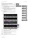
KW DEMAND ALARM
PICKUP: OFF KW
KVA DEMAND ALARM
PICKUP: OFF KVA
Range: OFF, 1 - 100000
Increments of 1
Increments of 1
Increments of 1
Range: OFF, 1 - 100000
POWER FACTOR LAG
P/F TRIP: OFF
Range: .01 - 1.00, OFF
Increments of .01
P/F LAG TRIP
DELAY: 1.0 SEC.
Range: 1 - 120 SEC.
Increments of 1
KVAR DEMAND ALARM
PICKUP: OFF KVAR
Range: OFF, 1 - 100000
AMPS DEMAND ALARM
PICKUP: OFF AMPS
Range: OFF, 1 - 100000
Increments of 1
POWER FACTOR LAG
P/F ALARM: OFF
Range: .01 - 1.00, OFF
Increments of .01
P/F LAG ALARM
DELAY: 1.0 SEC.
Range: 1 - 120 SEC.
Increments of 1