JKSSS+ Series - 68
JKSSS+ Series 2.3 - 4.2KV
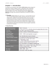
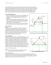
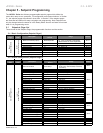
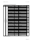
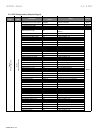
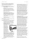
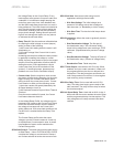
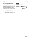
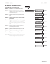
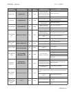
Sets the value
in the thermal register which represents a
motor running at the nameplate current (with
no overheating or negative sequence currents
present).
• Use the
data from the motor manufacturer’s specications.
When RTDs are used, this setpoint will be the
base point for the RTD biasing of the Thermal
Register.
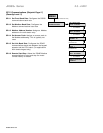
Use the data
from the motor manufacturer’s specications. This
setpoint denes the operating temperature rise of
the motor at full load amps or 100% load.
This represents
the maximum temperature the stator insulation
will withstand. The user may choose to use
the temperature setting of the insulation class
(selected in Setpoint Page 1) or enter a specic
maximum temperature. This value should not
exceed the stator’s insulation temperature. This
maximum temperature represents 100% thermal
capacity.
Always enabled.
It allows the soft starter to use the line current
imbalance information to bias the Thermal
Register.
When the setpoint
is set to ON the controller will calculate the k
constant factor for biasing the thermal register, or
the user may choose to assign the k value.
Allows
the level three password user to clear the thermal
register for emergency restarts.
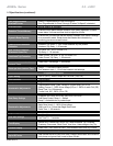
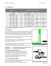
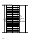
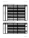
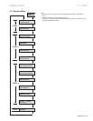
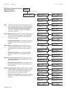
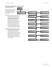
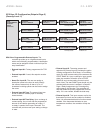
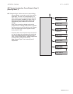
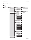
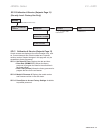
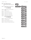
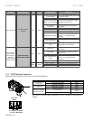
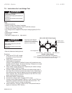
SP.12SystemSetpoints(SetpointPage12)
(SecurityLevel:3)
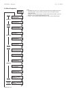
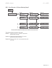
This setpoint group
allows the user to choose the default screen the
soft starter displays while the motor is running.
Select the metering page number (1-3), then
select the metering screen number. The range
varies depending on the selected page. To display
a default screen, program the following two
setpoints:
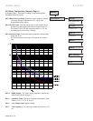
: Range is Page 1 - 3.
: If Page 1 is selected
as the default page, then Screens 1- 10 are
available. If Page 2, Screens 1-29 are available.
If Page 3 is selected, then Screens 1-6 are
available. (See Metering Menu, MP.1, for screen
number assignment.)
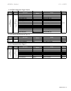
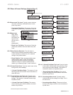
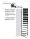
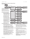
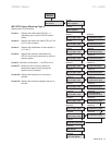
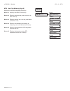
Congures the RTD failure alarm and the
thermal register alarm.
If enabled, and an RTD
shorts or open, an alarm occurs.
Sets a level in the
thermal register to generate an alarm when the
Thermal Register Capacity Used has exceeded
this level.
The amount of time that
the Thermal Register Used must exceed the
setpoint before an alarm condition will occur.
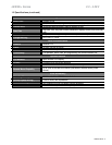
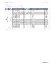
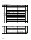
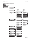
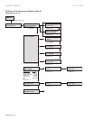
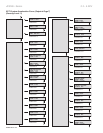
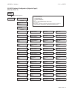
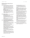
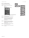
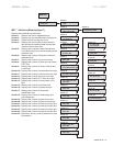
This
setpoint group will congure the thermal register
and indicate to the soft starter which inputs to use
when thermal modeling.
Enter the time from the motor
manufacturer’s specication sheet or use the time
dened by the OL Class. This setpoint is used to
dene the thermal capacity of the motor.
Enter the amount of time
specied by the motor manufacturer or use half of
the time dened by the OL Class.
: The time the motor
requires to cool down after it has stopped. Use
only the data provided by the motor manufacturer.
This setpoint is used to congure the cooling rate
of the thermal register.
The amount of
time the motor requires for cooling down while
running. Use only the data provided by the motor
manufacturer.
When RTDs are
used, the soft starter can be congured to use the
measured cool rates from the RTDs instead of the
programmed settings. This setpoint should only be
enabled when RTDs are present.