


JKSSS+ Series - 15
JKSSS+ Series 2.3 - 4.2KV
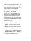
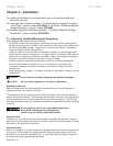
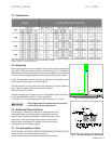
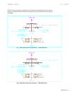
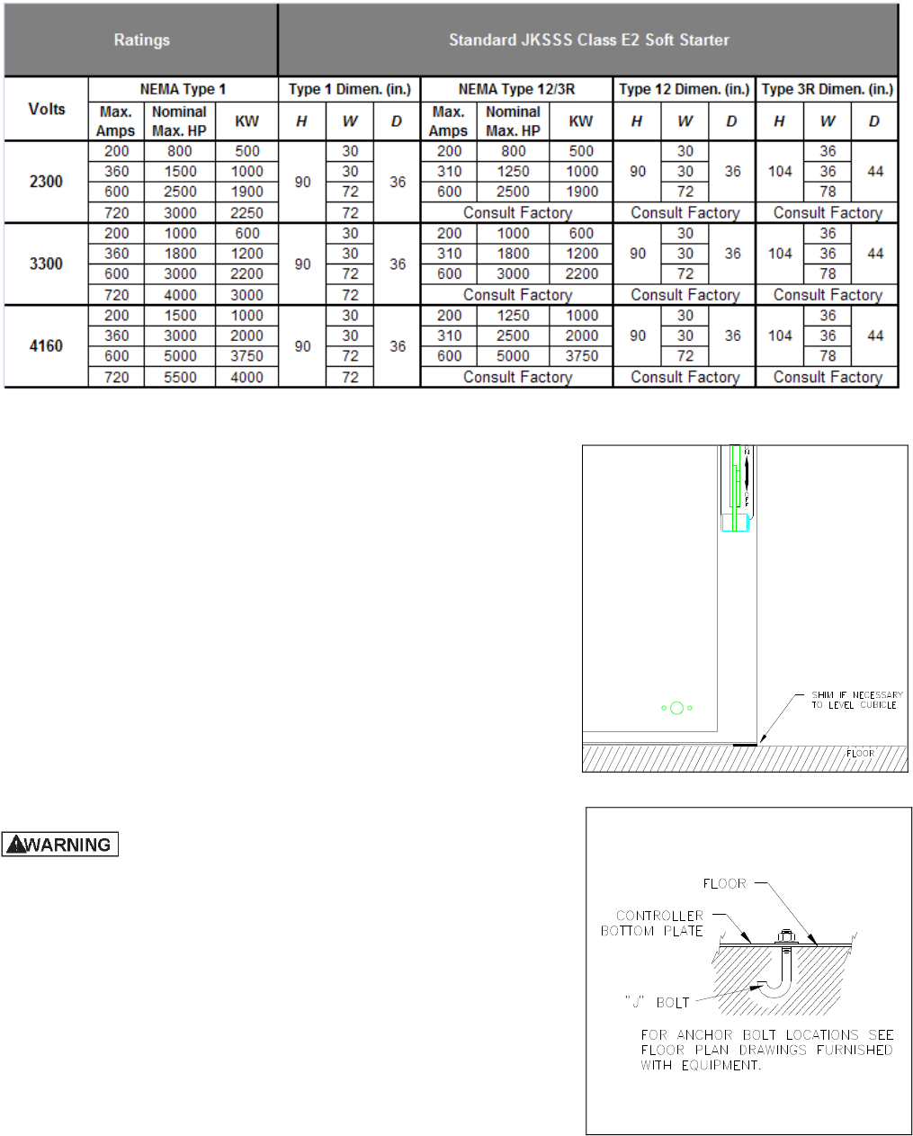
2.4 - Dimensions
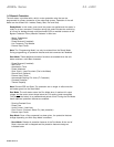
2.5 - Mounting
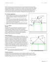
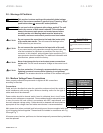
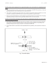
Each shipping section must be leveled and firmly secured to its supporting
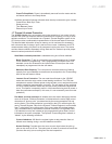
foundation. Steel shims may be used for final leveling (Fig. 3), if necessary.
When three or more shipping sections are to be arranged in one continuous
line-up, the center shipping section should normally be the first located.
Follow the equipment outline drawings to determine the location of the
mounting bolt holes and any conduit locations.
Sill channels may or may not be furnished, depending on order specifica-
tions. Refer to outline drawings furnished for location
of sill channels, if furnished.
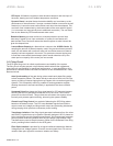
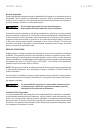
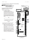
Various methods may be used to anchor the enclosure to the foundation,
including expandable inserts or “J” bolts embedded
in concrete. The recommended size for anchor bolts is 1/2" (Fig. 4).
Heavy Equipment. Enclosure must be securely
anchored to prevent tipping over.
2.6 - Additional Cabinet Entries
If conduit entry locations are required in areas other than the
removable plates, cover the electrical assemblies to prevent
metal filings from becoming lodged in areas which may cause
a reduction in the high voltage clearances or a short circuit.
After the work is completed, thoroughly clean the area and
reinspect the unit for foreign material.
2.7 - Pre-energization Check
AFTER INSTALLATION, BUT BEFORE ENERGIZING THE CONTROLLER
for the first time, follow the procedure below to
verify that the equipment is properly installed and functional.
Fig. 3 Leveling Using Shims
Fig. 4 Securely Anchor the Controller
Note: Dimensions are for reference only and subject to change.
Contact factory for exact dimensions.