


JKSSS+ Series - 18
JKSSS+ Series 2.3 - 4.2KV
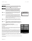
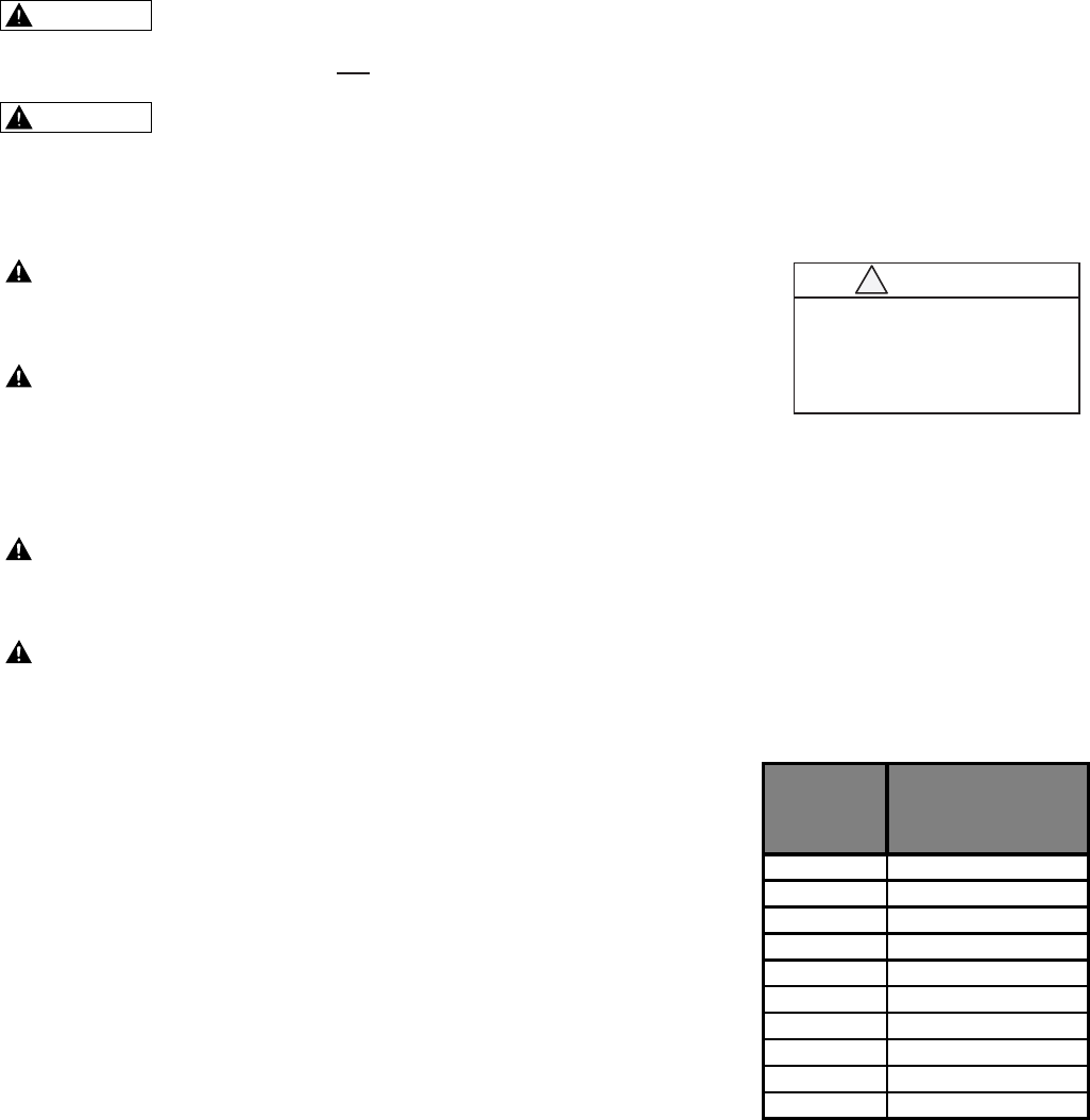
TorqueSpecsforMVPower
Connections
& Cautions
not
This will cause di/dt damage to the
SCRs when they are turned on.
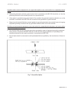
If you cannot avoid using capacitors across the power lines, they
must be located as far upstream as possible of the input line
contactor. In this situation, optional power factor correction (PFC)
caps contactor should be specied. For additional information and
specications, please contact the factory.
on the unit. This will cause excessive voltage to the control circuit
logic.
The arrestors should be mounted on the nearest utility pole.
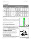
Use a properly calibrated torque wrench to tighten all MV connections
according to the chart.
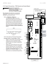
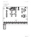
Connections
Cable and wire bundles that enter the controller enclosure should be routed to
avoid interference with moving parts. Minimum bending radius for the type of
cable used should be observed.
Power cables should be braced and/or laced to withstand short circuit forces
wherever such cables are unsupported. Power cables should be adequately sized
to carry the motor full load current in accordance with NEC requirements, and
have an adequate voltage rating. Cables should be dressed and terminated as
appropriate to the voltage class and cable manufacturer’s recommendations.
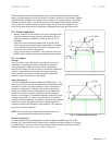
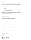
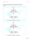
Main power bus (when provided) and horizontal ground bus are supplied with links
to join shipping sections together. These should be installed in accordance with Fig.
5 through Fig. 7.
All access covers, barriers, partitions, etc. that are temporarily removed during installation
must be replaced.
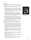
CAUTION
SCR DAMAGE
Do not connect (PFC) capacitors to the load side of
the unit.
Doing so will cause DI/DT damage to the SCRs when
energized.
!
1/4 - 20 6
3/16 - 18 12
3/8 - 16 18
7/16 - 14 30
1/2 - 13 45
9/16 - 12 68
5/8 - 11 90
3/4 - 10 150
7/8 - 9 240
1.0 - 8 245
CAUTION
CAUTION
CAUTION
CAUTION
WARNING
WARNING