


JKSSS+ Series - 24
JKSSS+ Series 2.3 - 4.2KV
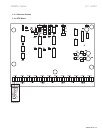
• Positions 5 and 6 accept dry, normally closed contact from the bypass contac-
tor for an At Speed indication. (Factory wired)
• Positions 7 and 8 are wired to the coil of the bypass contactor and energizes
and de-energizes the contactor. (Factory wired)
• Positions 9 and 10 are wired to the coil of the inline isolation contactor and
energizes and de-energizes the contactor.
All customer contacts are 960VA, 120VAC (Max) rated dry contacts.
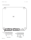
• -12 VDC power supply
• +12 VDC power supply
• Start = start is initiated to TCB board
• Fault = any fault has occurred
• Fuse Blown = disconnect open or blown fuse has activated
• PFC On = Power Factor Correction Capacitor contacts have energized
• Timed Out = Auxiliary time delay contacts have energized
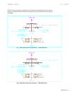
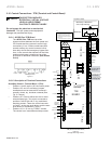
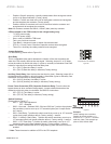
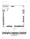
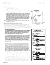
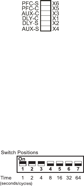
For the following, please refer to Figure 2-6.
This is a selectable delay period between the intiation of the start command and
when the CPU actually receives the start signal. Selecting Jumper X1 or X2 deter-
mines the method by which this delay (in cycles or seconds) is calculated. See SW3
below for instructions on setting the actual delay time.
• X1 = (DLY-C) Start time delay in cycles
• X2 = (DLY-S) Start time delay in seconds (Factory setting)
(from the time the start input is given). Selecting jumper X3 or
X4 determines the method by which this delay is calculated (cycles or seconds). See
SW4 below for instructions on setting delay time.
• X3 = (AUX-C) Auxiliary time delay in cycles
• X4 = (AUX-S) Auxiliary time delay in seconds (Factory setting)
(From the time the
bypass closes to when contacts change state). Jumper selection determines the
method by which this delay is calculated. See SW5 for instructions.
• X5 = (PFC-C) Time delay in cycles
• X6 = (PFC-S) Time delay in seconds (Factory setting)
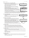
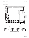
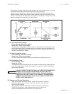
Please refer to Figure 2-7.
• SW1 = ON = Dual Adjustment
OFF = Disabled
• SW2* = Not used - Switches SW3, SW4 and SW5 are 7 position dip switches
that use binary code to count up to 127 seconds/cycles (see “Jumper Selec-
tion” above).
• SW3 = Start Delay; 7 position dip switch uses binary count up to 127 seconds/
cycles (see jumper selection above). Factory setting: 1 second.
• SW4** = Auxiliary (Start) Delay 7 position dip switch uses binary count up to
127 seconds/cycles (see jumper selection above). Factory setting: 1 second.
• SW5** = PFC time delay; 7 position dip switch uses binary count up to 127
seconds/cycles (see jumper selection above). Factory setting: 1 second.
* This switch interacts with the CPU programming when the Decel function is
enabled.
** These times are in addition to SP2 in the CPU setpoints.
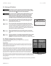
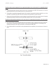
Switch settings are cumulative.
Setting dip switch positions 1, 2,
and 3 to “on” = 1+2+4 = 7 seconds
total time. Note: This example ap-
plies to SW3, SW4 & SW5.