46.22
Installing frame
•
Installation basically takes place in the reverse
order of removal.
•
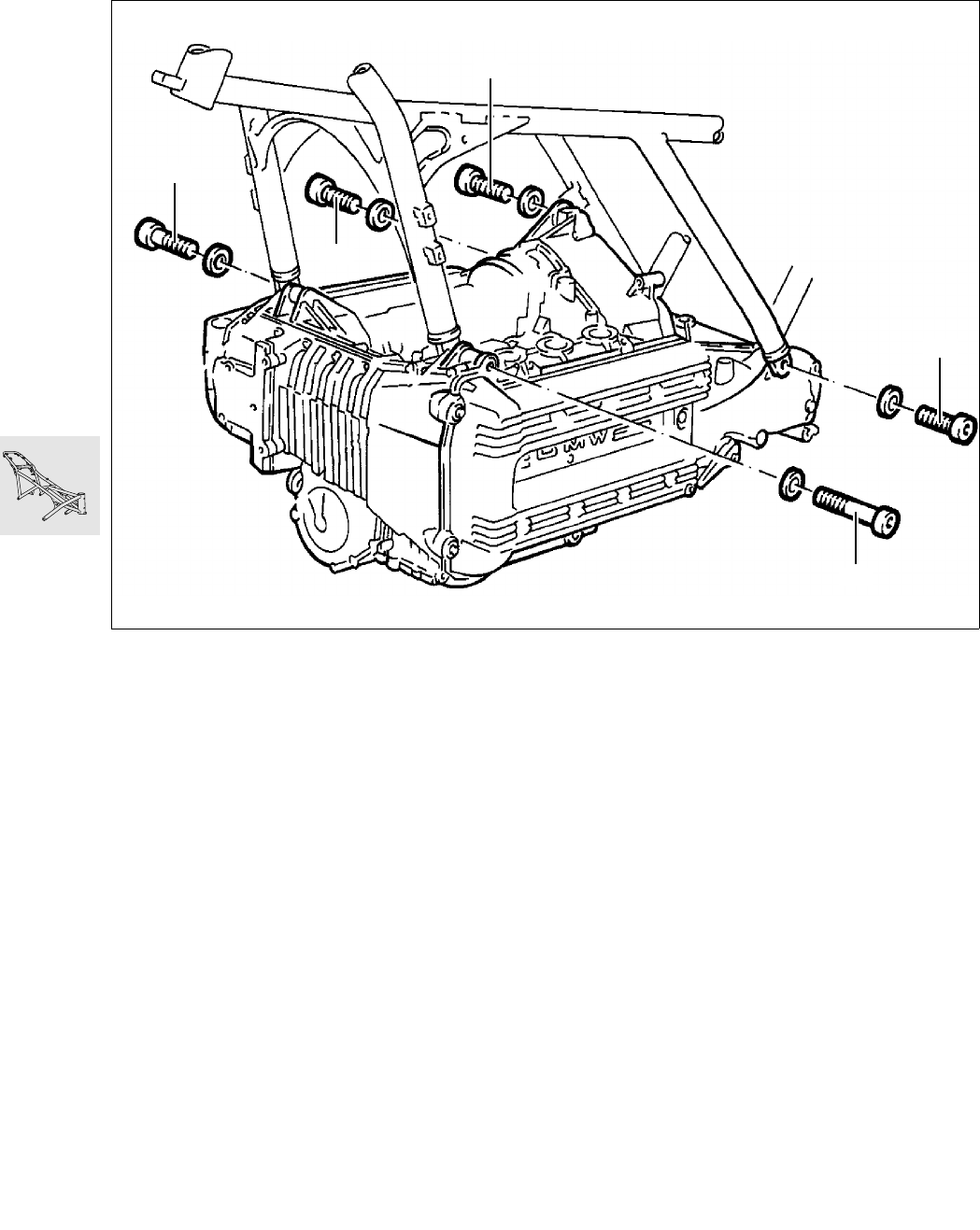
Place frame on drive train and firmly tighten
screws and bolts in the specified order.
1. Screw in all 5 screws loosely, i.e. not as far as
they will go. Fit a 1 mm thick spacer ring, inner
support ring at the front right between the cylin-
der head and frame strut.
2. Firmly tighten screws 1,4 and 3.
3. Measure distance at front left and fit outer sup-
port ring, firmly tighten screws.
4. Measure distance of mounting point on interme-
diate flange and firmly tighten screw.
X Tightening torque:
Frame to engine ........................................... 45 Nm
•
Install telescopic fork and adjust steering.
Setting torque:
Hexagon nut................................................ 12 Nm
New bearing adjustement procedure:
Pre-tighten hexagon nut to........................... 25 Nm
Move steering from stop to stop several times,
loosen hexagon nuts, retighten .................... 12 Nm
X Tightening torques:
Locking tube................................................ 65 Nm
Hexagon nut ................................................ 65 Nm
Clamping screws of fork bridge.................... 15 Nm
Clamping block for handlebar ...................... 22 Nm
Setting dimensions:
Clutch play at handlebar
lever....................... 4 ± 0,5 mm (0.157 ± 0.0197 in)
Cable length at clutch release
lever............................ 75 ± 1 mm (2.953 ± 0.04 in)
Accelerator cable play............. 0,75 mm (0.0295 in)
•
Carefully fill and bleed brake system
X Tightening torques:
Brake line to handbrake cylinder.................. 11 Nm
Brake line to distributor................................ 11 Nm
Brake line to brake caliper.............................. 7 Nm
Bleed screw................................................... 7 Nm
[ABS II] Pressure modulator to holder ......... 17 Nm
LT460300
2
3
4
1
5


