


USER MANUAL
ENGLISH
RS 2200 33019476(3)2010-02 A
19
The CAN-BUS data transmission line inner alarms are indicated by the general message “ERR” (2, Fig. I) plus a 4/5-digit code (4)
which specifi cally represents the alarm and some symbols indicating the alarm source (6) and seriousness (3). The visualisation
shown on the second line of the text identifi es the remedy taken by the system (5, Fig. I) depending on the alarm and nature of the
problem (1).
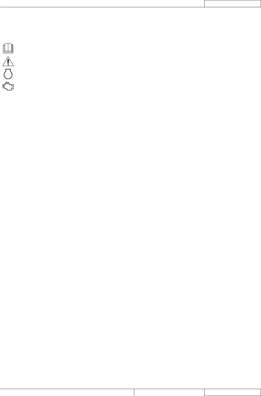
In the CAN-BUS data line alarm indication, the seriousness is indicated by four different symbols:
-
Not serious alarm. For the alarm coding see the Manual.
-
Serious alarm which does not cause the machine shutdown. Contact a Nilfi sk Service Center.
-
STOP
Serious alarms which causes the machine shutdown. Contact a Nilfi sk Service Center.
-
Particulate fi lter alarm. Contact a Nilfi sk Service Center.
The CAN-BUS inner alarms recognised and indicated on the display (32, Fig. E) can depend by different causes:
Diesel engine alarms, indicated by the visualisation (7, Fig. I), where the code (4) identifi es the alarm itself and must be –
communicated to the Nilfi sk Service Center. Among the alarms that causes the automatic engine stop, there are the following:
164.3 Fuel Rail Pressure Signal Error•
190.2 Faulty Engine Speed Sensor Error•
629.2 ECU Inner Communication Error•
651.3 Cylinder 1 Injector Circuit Malfunction Error•
652.3 Cylinder 2 Injector Circuit Malfunction Error•
653.3 Cylinder 3 Injector Circuit Malfunction Error•
654.3 Cylinder 4 Injector Circuit Malfunction Error•
657.3 Bank 1 Injector Circuit Malfunction Error•
658.3 Bank 2 Injector Circuit Malfunction Error•
Moreover, among the recognised engine alarms, there is the alarm for low effi ciency of the particulate fi lter(29, Fig. I), that do not
causes the automatic engine stop; however, in this case the operator must turn off the machine immediately. In this case, contact a
Nilfi sk Service Center.
Alarms for communication faults on the CAN-BUS line, indicated by the visualisation (26, Fig. I), where the number value (27) –
varies according to the fault and must be communicated to the Nilfi sk Service Center. The alarms are shown below:
SYSCODE.99 Disconnected AIA electronic board•
SYSCODE.01 The signal for manual accelerator is above the maximum allowed limit (track 1)•
SYSCODE.02 The signal for manual accelerator is below the minimum allowed limit (track 1)•
SYSCODE.03 The signal for manual accelerator is above the maximum allowed limit (track 2)•
SYSCODE.04 The signal for manual accelerator is below the minimum allowed limit (track 2)•
SYSCODE.05 The signal for manual accelerator is above the maximum allowed limit•
SYSCODE.06 The signal for manual accelerator is below the minimum allowed limit•
SYSCODE.08 There was no hopper sensor signal at the lifting•
SYSCODE.09 The difference between track 1 signal and track 2 signal exceeds the maximum limit•
ACCESSORIES/OPTIONS
In addition to the standard components, the machine can be equipped with the following accessories/optional, according to the
machine specifi c use:
Road sweeper version: –
Brooms with harder or softer bristles are available, according to the ground conditions.•
Camera kit•
Lifting jack•
Fire extinguisher kit•