


USER MANUAL
ENGLISH
RS 2200 33019476(3)2010-02 A
7
MACHINE DESCRIPTION
OPERATION CAPABILITIES
This sweeper has been designed and built to be used by a qualifi ed operator to clean (by sweeping and suctioning) roads, smooth
and solid fl oors, in civil and industrial environments, and to collect dust and light debris under safe operation conditions.
CONVENTIONS
Forward, backward, front, rear, left or right are intended with reference to the operator’s position, while on the driver’s seat (15, Fig.
E).
DESCRIPTION
Description of standard control panel
(See Fig. D)
Armrest mounting knob1.
Throttle lever2.
Parking brake3.
Brake pedal4.
Accelerator pedal5.
Ignition key6.
Speaker prefi tting7.
Left/right broom dust control system nozzle valve8.
3rd broom dust control system nozzle valve9.
Suction inlet dust control system nozzle valve10.
Forward/reverse gear selector11.
Cigarette lighter12.
Audio unit housing (prefi tting)13.
Ceiling light14.
Joystick safety lever15.
Electrical panel (*)16.
Safety belts17.
Brake fl uid tank18.
Joystick19.
Steering column20.
Hazard warning light switch21.
Combination switch (**)22.
Cab air fl ow control knob23.
Climate control system activation and temperature control 24.
knob
Heating temperature control knob25.
Driver’s seat26.
Passenger’s folding seat27.
Seat horizontal position control lever28.
Seat springing control knob29.
Seatback control lever30.
Broom lowering/widening switch31.
Pocket32.
Tool box33.
Identifi cation plate34.
Seat height control lever35.
Vent36.
Armrest37.
Skirt opening push-button38.
Skirt closing push-button39.
3rd broom arm left shifting push-button40.
3rd broom arm right shifting push-button41.
3rd broom arm extension lowering push-button42.
3rd broom arm extension lifting push-button43.
3rd broom tilting push-button +44.
3rd broom tilting push-button -45.
3rd broom rotation direction selector46.
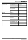
Description of standard control panel
(See Fig. E)
Turn signal indicator light1.
Hydraulic system oil high temperature, clogged hydraulic 2.
system oil fi lter and hydraulic system fault warning light
Parking brake warning light3.
Engine oil pressure warning light4.
Clogged air fi lter warning light5.
High beam indicator light6.
Engine glow plug pre-heating warning light7.
Lifted hopper warning light8.
Battery warning light9.
Running light indicator light10.
Water-in-fuel warning light11.
Engine speed adjustment potentiometer (working mode)12.
Broom speed adjustment potentiometer (working mode)13.
Sun visor14.
Steering wheel15.
Cab rear working light/suction inlet working light switch16.
Running light/low beam switch17.
Dashboard18.
Emergency push-button19.
Steering wheel position locking lever20.
Speed change switch (only for machines with speed 21.
change system)
Hopper dumping/return switch22.
Display scroll button23.
Hopper lifting switch24.
Front working light switch25.
Check engine warning light [it can turn into different 26.
colours (red, fl ashing red or orange) depending on the
fault].
Front leaf spring height control switch27.
Water pump switch28.
Suction fan, broom rotation and suction inlet/broom 29.
lowering switch
Suction fan switch30.
Hydraulic system enabling switch31.
Display (***)32.
See the electrical panel components below.(*)
See the combination switch functions below.(**)
See the display functions below.(***)