


10.24
ELECTRICAL
9923142 - 2011 RANGER RZR / RZR S / RZR 4 Service Manual
© Copyright 2010 Polaris Sales Inc.
CHARGING SYSTEM
Current Draw - Key Off
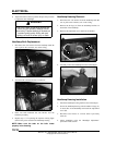
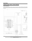
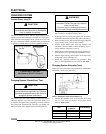
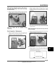
Connect an ammeter in series with the negative battery cable.
Check for current draw with the key off. If the draw is excessive,
loads should be disconnected from the system one by one until
the draw is eliminated. Check component wiring as well as the
component for partial shorts to ground to eliminate the draw.
Charging System “Break Even” Test
The “break even” point of the charging system is the point at
which the alternator overcomes all system loads (lights, etc.)
and begins to charge the battery. Depending on battery condition
and system load, the break even point may vary slightly. The
battery should be fully charged before performing this test.
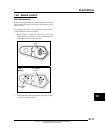
1. Using an inductive amperage metering device, (set to DC
amps) connect to the negative battery cable.
2. With engine off, key switch and lights in the on position,
the ammeter should read negative amps (battery discharge).
3. Shift transmission into park and start the engine. With the
engine running at idle, observe meter readings.
4. Increase engine RPM while observing ammeter and
tachometer. Note the RPM at which the battery starts to
charge (ammeter indication is positive).
5. With lights and other electrical loads off, the “break even”
point should occur at approximately 1500 RPM or lower.
6. With the engine running, turn the lights on and depress the
brake pedal to keep brake lights on.
7. Repeat test, observing ammeter and tachometer. With
lights on, charging should occur at or below 2000 RPM.
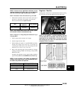
Charging System Alternator Tests
Three tests can be performed using a multi-meter to determine
the condition of the stator (alternator).
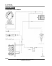
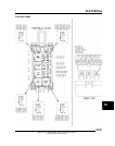
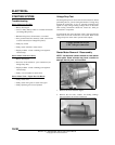
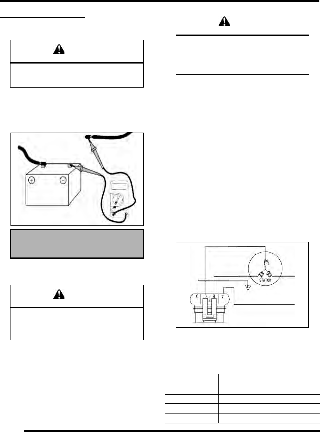
TEST 1: Resistance Value of Each Stator Leg
1. Measure the resistance value of each of the three stator
legs: Y1 to Y2, Y1 to Y3, and Y2 to Y3. Each test should
measure: 0.19 ± 15%
CAUTION
Do not connect or disconnect the battery cable
or ammeter with the engine running. Damage will
occur to electrical components.
Current Draw - Key Off:
Maximum of .01 DCA (10 mA)
CAUTION
Do not allow the battery cables to become
disconnected with the engine running. Follow the
steps below as outlined to reduce the chance of
damage to electrical components.
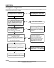
Current Draw Inspection
Key Off
WARNING
Never start the engine with an ammeter
connected in series. Damage to the meter or
meter fuse will result.
Do not run test for extended period of time.
Do not run test with high amperage accessories.
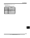
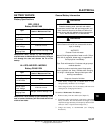
Test
Connect Meter
Leads To:
Ohms Reading
Battery Charge Coil Y1 to Y2 0.19 ± 15%
Battery Charge Coil Y1 to Y3 0.19 ± 15%
Battery Charge Coil Y2 to Y3 0.19 ± 15%
Y1
Y2
Y3